
Spot Welding
Questions and Answers
To start this off “RO” stands for Reverse Osmosis. This is a filtration process that uses a semi permeable membrane to filter out larger particles in the water. It removes most minerals. “DM” stands for Demineralized Water. It is also called Deionized water. It also removes the minerals from the water. As the name implies the ions are removed. The pro for both is they produce pure water.
AWS has a standard for water used in resistance welding equipment:
AWS Standard J1.2M/J1.2:2016 Guide to the Installation and Maintenance of Resistance Welding Machines
Yes, upslope might help in the reduction of expulsion or spatter during resistance welding.
In another article: WHAT IS UPSLOPE IN RESISTANCE WELDING
It was described that the lower power applied during upslope gives the components a chance to anneal and relax and come into full contact before full power is applied. This reduces the possibility for material expulsion. An example is poor alignment or badly formed projections can sometimes be helped with upslope.
The answer is yes. MFDC can be used to heat 10 mm bars.
In this application the equipment could be running nearly continuously. In the design of the equipment care must be taken to make sure the equipment is cooled adequately to insure it does not overheat. Additionally the MFDC equipment must be sized properly.
Properly cooled and sized MFDC will handle this job nicely and perform well.
This is a classical application of Joules Law:
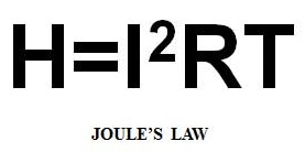
The heat is being generated by the resistance to the flow of current through the material.
Reference: RWMA, Resistance Welding Manual 4th Edition
Voids and cracks are not desirable in any resistance welding nuggets. In some material systems there is a tendency for cracks to form – such as Aluminum. In other materials oxides and surface impurities can end up in the nugget and voids or cracks form. Some cracks or voids form due to the volume expansion and contraction from liquid to solid state.
Depending upon the material and product and the industry there are specifications. Aircraft has specifications. Automotive has specifications. Individual companies have specifications.
Per AWS D8.1 Specification for Automotive Weld Quality – Resistance Spot Welding of Steel
Automotive specifies that cracks or voids lengths combined in the specified weld nugget area cannot exceed 25% of the nugget width. Therefor 1/3rd the nugget diameter is not acceptable in the automotive industry.
Per the definition of the Resistance Welding Manufacturers Alliance:
RESISTANCE WELDING IS THE JOINING OF METALS BY APPLYING
PRESSURE
AND PASSING
CURRENT
FOR A LENGTH OF
TIME
THROUGH THE METAL AREA WHICH IS TO BE JOINED
Spot welding is one of the four resistance welding processes as defined by the Resistance Welding Manufacturing Alliance. The four processes are:
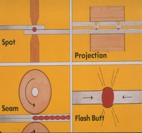
THE FOUR RESISTANCE WELDING PROCESSES
Page 21 of 44
Have a Question?
Do you have a question that is not covered in our knowledgebase? Do you have questions regarding the above article? Click here to ask the professor.