
Spot Welding
Questions and Answers
This question is getting into the area of physics and varies with the frequency of the input power.
The core is based upon flux density and can be calculated based upon physics calculations found in text books presented here.
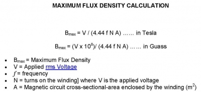
Any further discussion is beyond the scope of this forum.
Contact a resistance welding transformer manufacturer for additional assistance.
The answer to this question is – it depends upon the geometry/design of the part, the nut being welded and safety. M6 weld nuts come in many shapes and sizes.
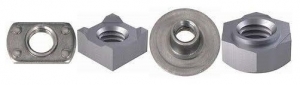
Assorted M6 Weld Nuts
Workpieces also vary in shape and size. Clearance for the electrodes will be determined by the geometry of the parts involved and the fixtures and tooling being used. There is no set value for spacing other than clearance to load the parts safely and not too much clearance to make the travel time too long for the electrodes to close.
After part design and clearance are determined what is left is safety and time. Time considerations are determined by the welding and loading equipment capability and the plant investment in tooling, automation and other factors.
Safety of personnel operating the equipment is a factor that must be considered in the design and layout of the equipment. Various safety codes could apply to the operation and determine pinch point, light curtain, lock out or other safety needs. A starting point to determine these needs could be ISO 12100 Safety of machinery — General principles for design — Risk assessment and risk reduction.
Automated or manual nut welding operations all require evaluations for safety and part clearance to determine the proper electrode opening. No two operations are alike therefor there is not a set answer to this question.
For economics and safety one would not open any more than is necessary to load the part. Safety must be built in to keep the operators hands out of the pinch points. This reduces electrode travel time and reduces room for an operator to be hurt.
Reference: ISO 12100 Safety of machinery — General principles for design — Risk assessment and risk reduction.
Spot welding stainless steel to titanium is definitely in the world of research. Both materials can be resistance welded. Data is available in AWS C1.1. It does not cover resistance welding the two together.
It is known that both materials are reactive and sensitive to heat. Titanium expulsion can be very exciting.
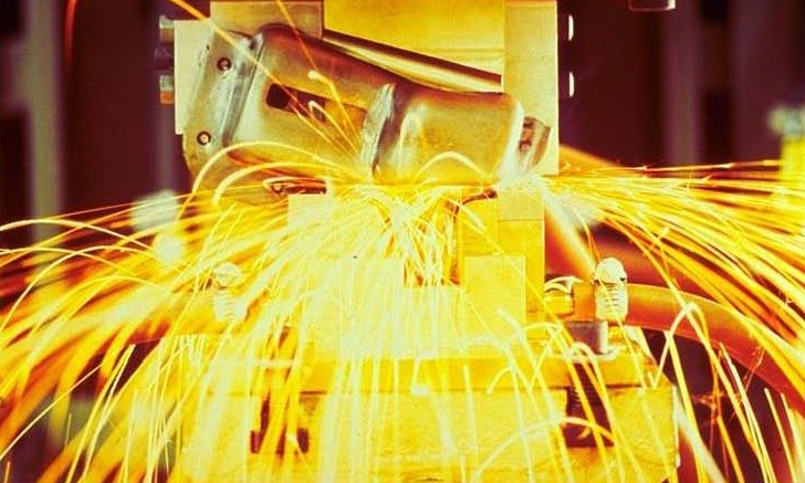
EXCESSIVE EXPULSION
A serious shield for protection from expulsion would be in order. Stainless is austenitic and can subject to interface cracking. On the positive side they both heat up and spot weld readily.
Some digging in the research found that using an interlayer of aluminum might not work due to the formation of some undesirable intermetallic phases. Further research found that magnesium might be used in laser welding and copper was being used for friction stir welding. Both might be worth a try as a resistance braze medium if a spot weld cannot be developed using the data from AWS C1.1.
If a brazed joint is acceptable then consider that both titanium and stainless are being brazed to themselves in industry. Braze alloys exist. Contact a brazing alloy supplier and search for a braze alloy that might be suitable to join them together. A resistance welding machine can do the job depending upon the quantity design and engineering specifications.
Reference: AWS C1.1, Recommended Practices for Resistance Welding
RWMA - Resistance Welding Manual 4th Edition
In this scenario we will base the schedule on the governing metal thickness (GMT– the thinnest outside sheet), which is 1mm. For simplicity there was a chart readily available at 0.045 in material, which is 1.15mm.
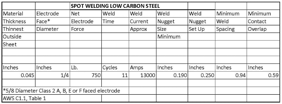
This AWS C1.1 schedule calls for a 1/4inch weld face, 750 lbs force and 13000 amperes for 11 cycles.
Since the materials are dissimilar in thickness adjustments will need to be made to balance the heat and get the nugget to form evenly at the interface. This heat balancing is done with electrode face changes or electrode material changes. One wants to cool the thick side to move the nugget toward the thin material. Or you can heat the thin sheet.
For additional information see article:
WHAT IS POOR HEAT BALANCE IN RESISTANCE WELDING
The issue of pressure vs force is they are directly related. Force is measured in pounds in the above schedule and the pressure applied is that same pounds applied to the ¼” weld face (pounds/in2).
Reference: AWS C1.1 Recommended Practices For Resistance Welding
This question can be answered with two types of equipment. A package or fixture type transformer can be manufactured with either one or two secondary outputs.
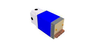
FIXTURE TYPER TRANSFORMER TWO SECONDARYS
When two secondarys are used they by transformer design will fire with the same voltage. Thus is the current output will be the same as long as the two current paths are exactly the same. For the welds to be alike the materials being welded and electrodes must be alike and in the same condition. If any of these items vary the current flow will begin to vary between the two paths. If the currents vary too much the welds will start to vary. Generally this is not an issue.
However if one ignored the imbalance it could become a real issue and one weld or the other could become discrepant if material thickness, materials, coatings, cable condition, electrode wear, or water cooling were not maintained properly. Therefor for a fixture transformer material thickness, materials and coating are an issue that must be considered in double firing spot welding.
A second type of equipment that could be making single or double welds might be a Cascade welder. This is a control arrangement where multiple guns are being fired on a machine system individually by one control. Each gun has its own schedule but they are sequenced so that they fire in sequence to prevent multiple guns from firing at the same time. In this scenario material thickness and coatings are not a big issue because an individual schedule can be set for each weld to match the circumstances.
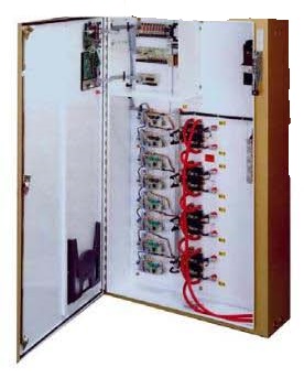
FOUR CASCADE CONTROL
This Cascade Control would be used to fire four individual guns with one control.
In place of this unit, four individual controls could fire the same four weld guns singly. If sequencing were desired the addition of a PLC or other timing function would be needed to control their sequence.
Below is a schematic of an application of a fixture type transformer in use.
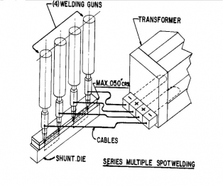
SERIES WELD USING FIXTURE TRANSFORMER
Reference: RWMA Manual- Fourth Edition, 19
Roman Manufacturing Inc
ENTRON Controls, LLC
Page 24 of 44
Have a Question?
Do you have a question that is not covered in our knowledgebase? Do you have questions regarding the above article? Click here to ask the professor.