
Projection Welding
Questions and Answers
The same nut weld part plated and unplated is welding with good strength but the plated version is failing the impact test. Without any other input one can only assume the plating has changed the welding parameters and the part is not resulting with the same final weld joint. It is either weak or brittle.
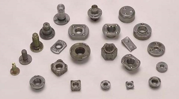
PROJECTION WELD PARTS
The first thought is that some heat energy is being absorbed by the coating being melted. That energy would normally have gone into the weld projection. Thus they have not heated up as much as in an uncoated part. This may lead to less potential set down and strength.
The second issue is the coating may be in the joint and acting as a braze joint. That is OK but it is not as strong as the desired projection weld and is likely to contain weld contaminants. In short it is not a desirable braze joint.
A schedule change is probably needed to ensure more projection weld set down and involvement on the coated part projections.
References: RWMA – Resistance Welding Manual 4th Edition
There are many variables in nut welding that can change. In your inquiry you stated that the material and nuts were the same. Are they?
Is this coated material? Is the coating the same everywhere all of the time? Is the material clean or oxidized consistently?
Projection weld nuts are known to have variable projections in size, shape and height.
Does the nut feed onto the locating pin properly or hang up once in a while?
Is the locating pin properly insulated? Has the insulation worn? Is current shunting through the pin?
Is the weld cylinder hesitating/hanging up and not moving fast enough?
Fast follow up for cylinders or servos is imperative for weld strength.
Is the tooling aligned properly for even touch down of all equal projections?
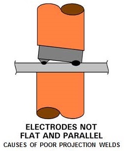
Projections missing or wrong size cause the same problem as above.
Have any shunts or cables begun to wear or insulation worn? Worn cables and shunts will definitely change the weld results.
I have pointed out many variables that obviously can affect the projection nut welding process when all appears to be running normally. Any or all can or will cause havoc with push off tests.
More in-depth discussions of these topics are discussed in other articles in this blog:
WILL UNEQUAL SHAPE PROJECTION CAUSE ISSUES IN PROJECTION WELDING?
WHAT IS FOLLOW UP IN PROJECTION WELDING?
HOW DOES ALIGNMENT AFFECT PROJECTION WELDING?
WILL OVERSIZED PROJECTIONS CAUSE ISSUES IN PROJECTION WELDING?
WILL UNDERSIZED PROJECTIONS CAUSE ISSUES IN PROJECTION WELDING?
WHAT ARE THE DO’S AND DONT’S FOR PROJECTION WELDING?
WHY DO I HAVE INCONSISTENT RESULTS NUT WELDING ON GALVANIZED STEEL?
References: RWMA – Resistance Welding Manual 4th Edition
AWS – AWS Standard C1.1 Recommended Practices for Resistance Welding
CMW Inc. Resistance Welding Products Catalog
I am not aware of projection welds being made under water. Seam welds are frequently made with water flooding. No reason that projection welds could not have water present. I expect that someone is using water in their process. Seam welds use water mainly for cooling not necessarily for expulsion.
Projection weld expulsion prevention should begin not at expulsion but at its source. Process, alignment, misalignment, bad insulation, bad/uneven projections, cylinder/force problems, bad follow up and other process problems. Address the issues listed in the following article before turning to water.
CAN A PROJECTION WELD CAUSE SPATTER OR EXPULSION?
References:
RWMA- Resistance Welding Manual 4th Edition
Projection weld nuts are used in many industrial applications. Many are piloted weld nuts as shown below.
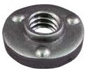
THREE PROJECTION WELD NUT WITH PILOT RING
To make a good projection weld several issues must be considered:
They are:
1. The purpose for the pilot on a weld nut: The short answer is to help protect the internal portion of the weld nut from expulsion and other foreign material while being welded. The tooling and part associated with the projection welding (PW) of forged or coined weld nuts (think solid projections) must be properly designed, to include ways to minimize expulsion getting into the threads. A proper pilot on the nut can help in this regard.
2. The tooling used is also really important: The pin package and other portions of the tooling must be robust, able to hold the part in a repeatable location, and place the weld nut accurately and centered on the hole. Items that need to be considered as part of this design are the gauge of the material being welded, the thickness of the nut, the height of the projections, and where electrical insulation is needed.
3. The proper size of the hole in the part: The stated clearance value of 0.002” is too small for the size of the application. One PW design standard I am familiar with specifies for an M10 piloted weld nut (close to the 3/8 nut in this question) a 15.0-15.15 mm hole Ø for a pilot on the nut, with a pilot of between 12.4 – 12.7 mm Ø. The aforementioned standards would result in clearances of roughly double reported above.
4. The welding equipment must be capable, and the schedule proper for the application: This one is very application dependent. There is an article in the Welding Journal (Sep-2010 - RWMA Q & A) that might be helpful to address machine and weld schedule.
References: RWMA – Resistance Welding Manual 4th Edition
AWS – AWS Standard C1.1 Recommended Practices for Resistance Welding
Technical Input by - DONALD F. MAATZ Jr.
Milco Manufacturing Company
There are articles on constant voltage and constant current in this blog:
SHOULD CONSTANT CURRENT EVER BE USED FOR PROJECTION WELDING?
These explain the advantages of using constant voltage and constant current.
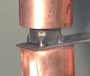
PROJECTION NUT WELD
This blog deals with the resistance welding process. It does not offer any input on manuals set up or maintenance of individual machines. Consult your local machine dealer or manufacturer for assistance.
Reference: RWMA Resistance Welding Manual 4th Edition
American Welding Society - ANSI Z49.1 Safety in Welding and Cutting and Allied Procsses - Available as free dowload on www.aws.org
Page 1 of 14
Have a Question?
Do you have a question that is not covered in our knowledgebase? Do you have questions regarding the above article? Click here to ask the professor.