
Flash Welding
Questions and Answers
Flash welding uses the work piece as the electrode. A clamp is used to hold the parts and apply force. The entire cross section of the work piece is welded. It is in the timing and the application of force and current that is critical.
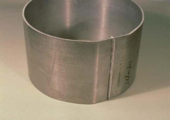
FLASH WELDED WHEEL RIM
Current initiates with the intent of creating an arc between the two workpieces. This generates large amounts of heat on the entire work surface. Large amounts of flash are generated. This flashing action cleans and heats both part mating faces. Then force is applied as the arc current is being terminated. The hot parts are upset and joined together. Power is turned off. Part cools and force is removed. This flash weld joint is very strong.
The upset distance and weld speed is not something that can be calculated. Trial and error tests are the best method to develop the proper settings for the machine and part combination.
The RWMA “Resistance Welding Manual 4th Edition” Section 5 has a considerable amount of information on upset speeds and distances and the variables that are present. For example, RWMA suggests a common upset distance is ½ the part thickness. However, this will vary by alloy up to 1-1.25 times the thickness for high temperature alloys. Aluminum is 50% greater than steel.
Below is a chart which lists the variables for flash and butt welding and how they can affect the final product.
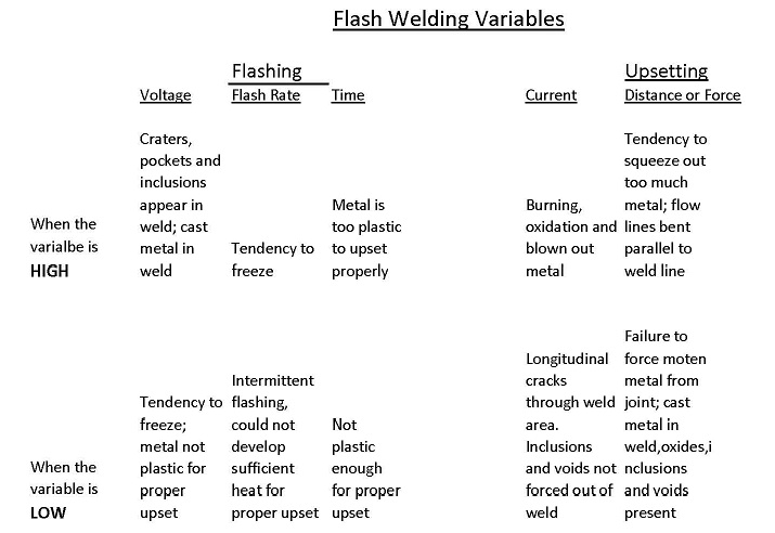
Refer to the information in the RWMA manual and then perform some trial and error testing to develop the proper settings.
Other blog articles: Can flash welding variables affect the weld?
References: RWMA – Resistance Welding Manual 4th Edition
In the past most flash welders were AC. AC controls are relatively inexpensive compared with DC or mid frequency (MFDC) controls. If you have AC equipment and power is not an issue it would be logical to use AC if possible. AC controls with SCR’s are very robust and will operate for many years.
Flash welding requires a lot of power. If the power requirements exceed AC’s practical capability, then DC or MFDC become the proper choice. DC by its nature is rather large equipment. In the last few years Mid Frequency power supplies have entered the market. Initially they had a problem with the spikes associated with arcing. This has been worked on and now MFDC can be used for flash welding.
The question raised is about an 18V/9000Amp application. There are 17V secondaries in use with MFDC. Yes, 18V/9000Amp is a workable MFDC application.
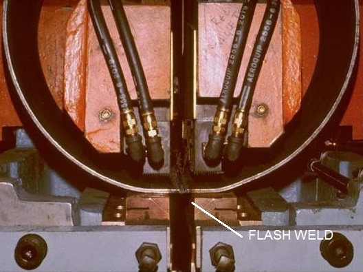
FLASH WELDER
Compared with an AC application MFDC will reduce the power requirement substantially and could become economically advantageous over AC. MFDC also offers very fine control of the actual weld cycle which can be helpful. MFDC controls can result in higher quality levels and more good parts.
If you were considering the need for DC equipment, MFDC may be a better choice because it delivers the DC current, reduces the total plant power load and reduces the size of the flash welder transformers.
Ref: RWMA Resistance Welding Manual Section 5
The affect of flash and butt welding on the electrical circuit of the machine and plant facility depend upon the size of the job being welded. Nominally flash/butt welders use power similarly to a spot welder. A band saw butt welder does not draw much power. A butt welder in a wire draw shop could be relatively small.
A flash welder for off-road vehicle wheels or large trucks requires considerable power. Butt or flash welding railroad rails together would require considerable power.
The smaller jobs would have no more affect than a resistance spot welder. The larger butt or flash welders to do RR rails would require a substantial dedicated buss. There would be potential for large draw on the buss if not sized properly.
In flash welding wheel rims there are two potential paths for the current to flow. One is across the faying surface being flash welded. The other is through the circumference of the material from one electrode all the way around to the other electrode. This is potentially a dead short. The question is which path has the least resistance? That will be the current path.
WHEEL RIM WELDER
Most hot upsetting/butt welding applications are AC. AC controls are relatively inexpensive compared with mid frequency (MFDC) controls. If you have AC equipment and power is not an issue it would be logical to hot upset with AC. AC controls with SCR’s are very robust and will operate for many years.
Hot upsetting can require a lot of power. This could be a large requirement on the plant electrical system. If the plant does not have the power without a large investment in new power, MFDC controls would reduce this power requirement substantially and could become economically advantageous over AC. MFDC also offers very fine control of the actual weld cycle which can be helpful. MFDC controls can result in higher quality levels and more good parts.
If you were considering the need for DC equipment MFDC may be a better choice because it delivers the DC current, reduces the total plant power load and reduces the size of the butt welder transformers.
Page 1 of 3
Have a Question?
Do you have a question that is not covered in our knowledgebase? Do you have questions regarding the above article? Click here to ask the professor.