
Spot Welding
Questions and Answers
This is a very common material in the industry and there are many publications with weld schedules available. These schedules were developed on specific machines and material with specific chemistry and properties. Your machine and material will vary. These schedule settings will produce a weld but may require some adjustment to produce the best results for your particular situation, material and equipment.
It is not a perfect world but in a perfect world one wants to maintain a constant current density at the electrode face. Therefor as the electrode face grows, the current should be increased to match this growth. A simple chart demonstrates this and is published in many places. Here is an excerpt:
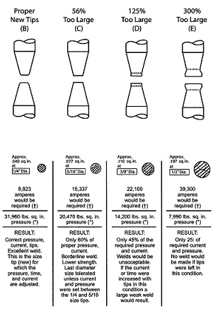
This Figure demonstrates the growth of the weld face and the need to increase the weld current at a rate to maintain the original current density.
IS DC OR MFDC BETTER OR PREFERRED OVER AC IN SPOT WELDING?
The answer to this question depends upon the product being welding, the quality standard, power availability and equipment intended for the job. If this is to be a robot/automation operation MFDC may be the best choice. It will reduce the weld gun weight. If the plant has a power shortage again MFDC comes to the forefront. It is three phase which will balance the load and it will use less total power than AC.
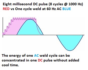
If strict quality standards are necessary MFDC in (ms) may also lend itself to more fine control.
DC has not been mentioned since standard DC has mostly been replaced by MFDC due to DC’s costs and physical size.
This does not rule out AC. It is tried and true. AC is more robust with longer life and is more familiar to many facilities. If you use press welders, power is not an issue and work with normal quality standards AC is a good choice. If the facility already has many other AC units for backup AC would be a very good choice.
For a complete comparison and discussion of the two topics read another article in this blog:
To extend this question, if the schedule can be the same will there be issues in a push/pull weld arrangement? The two materials are similar. The cold rolled is harder and may distort a little from the heating. The hot rolled is softer. Both are relatively easy to spot weld. The difference in their individual weld schedules is very small maybe 2%. Yes, they should run on the same weld schedule assuming similar thicknesses and compositions.
Yes, it could be a power problem. It could be a pressure/force problem also associated with the lack of adequate plant supply. There are many other machine components and schedule issues that should not be overlooked.
These are two articles on related subjects discussed in this blog:
WHY DO WELD NUGGETS VARY DURING A SHIFT?
WHY DO THE FIRST PARTS AFTER A BREAK HAVE UNDERSIZED WELD NUGGETS?
Page 18 of 44
Have a Question?
Do you have a question that is not covered in our knowledgebase? Do you have questions regarding the above article? Click here to ask the professor.