
Spot Welding
Questions and Answers
It will be assumed that a 1000 volt primary supply is connected to the primary of a resistance welding transformer. The question is should this produce amperage on the secondary? Assuming that the control is functioning, wiring is correct and the transformer is good the answer is yes. There should be voltage and current at the transformer secondary terminals. The amount depends upon the equipment.
This means that many items need to be verified to insure that all is correct. If all is correct and there is no voltage and current present at the secondary, back up the circuit and test.
Is there voltage at the primary?
Is the transformer grounded properly? If the transformer is failing to ground it should have tripped a breaker. In either case investigate the transformer.
Is there a properly sized breaker on the system?
If the transformer is good, move up a level.
Then back up another lever head to the control etc. Check all connections and fuses. The control could be failing and not activating the SCR. A component has failed or is wired improperly somewhere. Search till it is found.
A conductor, fuse, component has failed somewhere in the system. A 1000 volt connection will flow if connected and the components are functioning properly.
Reference: RWMA - Resistance Welding Manual 4th Edition
AWS - J1.2 Guide to Installation and Maintenance of Resistance Welding Machines
Automated lines are very common in today’s factory. In the resistance welding world this means the parts are automatically brought to a work station. A robot with a weld gun is activated and makes a series of welds. It pulls back and waits or dresses the electrodes at an automated dressing station during the part index time. Sometimes these dresses happen after each part, sometimes after several parts. The goal is that the electrodes are generally dressed frequently but lightly and kept fresh for a long life.
These automated dressing systems are incorporated into the weld systems. Often the dressers are built and designed by the system integrator. In some cases the integrator incorporates dressers manufactured by others into their systems.
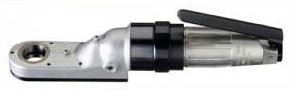
PEUMATIC HANDHELD DRESSER - NOT AUTOMATED
In either case automated equipment systems are outside the area of this forum.
To find information on this subject contact your local equipment or system supplier or resistance welding distributor.
RESOURCE: RWMA - Resistance Welding Manufacturing Alliance has a listing of member companies who could be of assistance in this endeavor.
Several sources are available to select the electrode material for spot welding. If the material to be spot welded it known you are ready to proceed. Two sources for information are:
AWS Standard C1.1 Recommended Practices for Resistance Welding
RWMA – Resistance Welding Manual 4th Edition
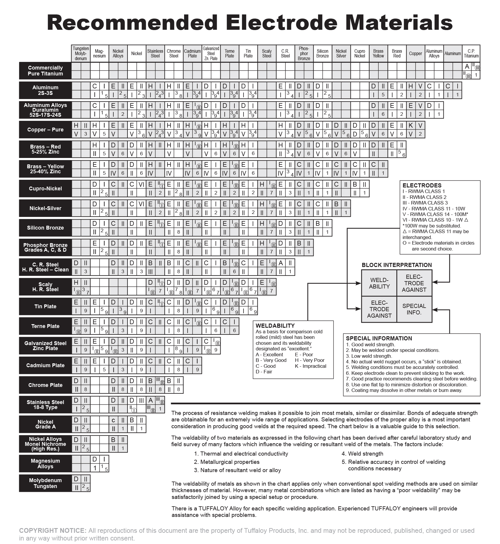
Stainless steel is a relatively strong resistive material. This means that in electrodes we will need strength but not necessarily a high conductor. The recommended electrode material for stainless is RWMA Class 3. This is the strongest of the copper alloy electrode materials but still has good electrical conductivity. The second choice would be RWMA Class 2 which is not as strong but has better conductivity.
The chart below shows electrode material selections for various spot weld material combinations.
For additional information on this topic see article:
HOW DO I SELECT THE PROPER ELECTRODE MATERIAL FOR SPOT WELDING?
Reference: AWS C1.1 Recommended Practices for Resistance Welding
RWMA Resistance Welding Manual 4th Edition
Tuffaloy Products Catalog and Website
CMW Inc. Catalog
Pressure is one of the major components of the welding process Pressure, Current & Time (PCT). In most weld schedules pressure is called out as a force value. Pressure is this same value as force but applied to the surface area of the electrode contact face.
See the article - How are force and pressure related?
The relationship between pressure and the heat generated during resistance welding is well established. It is represented by the figure below.
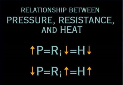
Increasing pressure will reduce the overall resistance and decrease the heat generated. Conversely reducing pressure will increase the resistance and increase the heat. The question asked was how does force affect the process. Pressure is that same force applied to a specific surface area (lbs/in2). Therefor increasing or decreasing force has the same effect as pressure.
To answer this inquiry we will start with a previously published question and expand upon it.
“WHAT IS THE DEFINITION OF RESISTANCE WELDING”
Per the definition of the Resistance Welding Manufacturers Alliance:
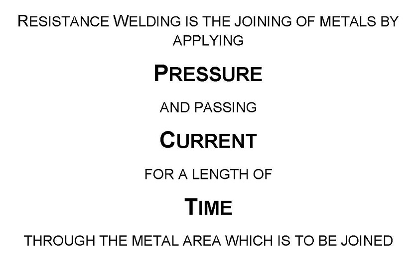
To expand upon this PRESSURE is provided by mechanical means of pneumatic or hydraulic cylinders, servos, cams and sometimes manually. Normally it is measured in pounds, kilos or equivalent. It is applied in sufficient amount to contain and control the weld to a specific desired area, before the current is applied. CURRENT is supplied by the control and transformer. The transformer does just that transforms relatively small current input from the buss to many thousand amperes needed for resistance welding at people safe low voltages. The control determines the amount of CURRENT and the TIME.
Heat is generated according to JOULES LAW.
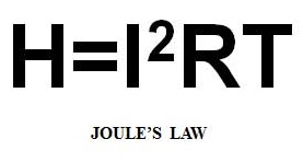
The heat is generated by the current squared times the resistance multiplied by the time. It is the current flowing through the area to be joined for a length of time and the resistance at that joint which generates heat to make a joint. The force holds all of this together and forges the joint as it forms and cools down.
AC resistance welding would use AC current and transformers for the power in resistance welding. Most rocker arm and press welders have been manufactured with AC power supplies. The equipment can also be DC direct current. In the last thirty years MFDC mid frequency direct current is has become the go to equipment for automated robotic systems and many other applications.
There are many articles published in this forum about the advantages and disadvantages of the AC, DC and MFDC systems. One can find these by performing a search on the home page of this forum.
Reference: RWMA – Resistance Welding Manual 4th Edition
Page 23 of 44
Have a Question?
Do you have a question that is not covered in our knowledgebase? Do you have questions regarding the above article? Click here to ask the professor.