
Spot Welding
Questions and Answers
This question can be answered with two types of equipment. A package or fixture type transformer can be manufactured with either one or two secondary outputs.
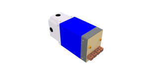
FIXTURE TYPER TRANSFORMER TWO SECONDARYS
When two secondarys are used they by transformer design will fire with the same voltage. Thus is the current output will be the same as long as the two current paths are exactly the same. For the welds to be alike the materials being welded and electrodes must be alike and in the same condition. If any of these items vary the current flow will begin to vary between the two paths. If the currents vary too much the welds will start to vary. Generally this is not an issue.
However if one ignored the imbalance it could become a real issue and one weld or the other could become discrepant if material thickness, materials, coatings, cable condition, electrode wear, or water cooling were not maintained properly. Therefor for a fixture transformer material thickness, material and coating are an issue that must be considered in double firing spot welding.
A second type of equipment that could be making single or double welds might be a Cascade welder. This is a control arrangement where multiple guns are being fired on a machine system individually by one control. Each gun has its own schedule but they are sequenced so that they fire in sequence to prevent multiple guns from firing at the same time. In this scenario material thickness and coatings are not a big issue because an individual schedule can be set for each weld to match the circumstances.
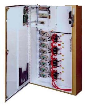
FOUR CASCADE CONTROL
This Cascade Control would be used to fire four individual guns with one control.
In place of this unit, four individual controls could fire the same four weld guns singly. If sequencing were desired the addition of a PLC or other timing function would be needed to control their sequence.
Below is a schematic of an application of a fixture type transformer in use.
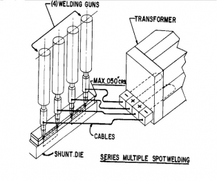
SERIES WELD USING FIXTURE TRANSFORMER
Reference: RWMA Manual- Fourth Edition, 19
Roman Manufacturing Inc
ENTRON Controls, LLC
In North America the common unit of measure for force is pounds (lb). AWS publishes force in units of Kilo Newtons (kn) and pounds (lb). Of course other parts of the world and even N America may use different but equivalent units of measure.
All of these force units (lb) may be converted into pressure units (psi) based on the area the force is being applied to.
Many electronic force gauges measure force and have the ability to read in the unit of measure desired.
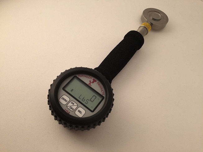
DIGITAL FORCE GAUGE
Pressure and Force are frequently confused in resistance welding. They are related terms. The force applied produces pressure at the face of the electrode. For example approximately 1600 lb-force will produce 32,000 psi/pressure on a ¼” electrode face.
Reference: AWS C1.1- Recommended Practices for Resistance Welding
TUFFALOY CATALOG, Rev 2017
In this scenario we will base the schedule on the governing metal thickness (GMT– the thinnest outside sheet) , which is 1mm. For simplicity there was a chart readily available at 0.045 in material, which is 1.15mm.
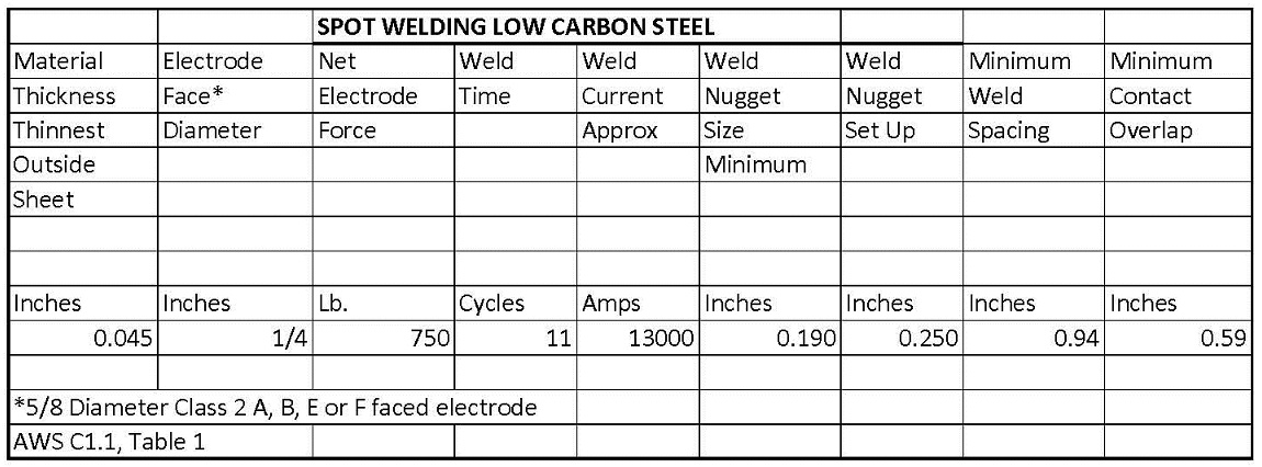
This AWS C1.1 schedule calls for a 1/4inch weld face, 750 lbs force and 13000 amperes for 11 cycles.
Since the materials are dissimilar in thickness adjustments will need to be made to balance the heat and get the nugget to form evenly at the interface. This heat balancing is done with electrode face changes or electrode material changes. One wants to cool the thick side to move the nugget toward the thin material. Or you can heat the thin sheet.
For additional information see article:
What is poor heat balance in resistance welding?Reference: AWS C1.1 Recommended Practices For Resistance Welding
All spot welding electrodes wear in the same manner. They mushroom - The nose diameter grows larger with use.
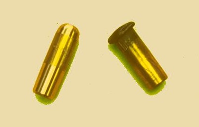
SEVERE MUSHROOMED ELECTRODE
The mushrooming does not change the schedule or settings of the welder but it does change the path the current takes into the part. The contact surface area grows as the electrode face grows. Therefor the same current is spread over a larger area and the weld zone is not as concentrated and cools down. The current density has reduced. With time the weld strength reduces and will fail to meet quality standards unless corrective measures are taken. The chart below demonstrates the change in electrode face versus current requirements.
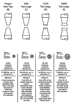
There are two methods to correct for this wear. One is to use the control to make regular increases in the current to match the face increase in size. The amount and frequency of these changes is developed by trial and error. If is usually a couple of amps each weld or several amps every 50 or 100 welds.
The other method is to dress (remachine) the electrode face back to the original diameter before it is too large. Then continue to weld. This can be done on the machine with automatic or hand dressers or remove and replace the worn electrode and reface on a lathe to return later to the weld line.
For additional information read Articles:
HOW DO I DETERMINE A TIP DRESSING FREQUENCY OR PROGRAM FOR A SPOT WELDING ELECDTRODE?
ON THIS SITE SEARCH FOR “DRESS”
Reference: RWMA – Resistance Welding Manual, 4th Edition
Pressure is one of the major component of the welding process Pressure, Current & Time (PCT). In most weld schedules pressure is called out as a force value. Pressure is this same value as force but applied to the surface area of the electrode contact face. See the article - How are force and pressure related?
Pressure is important because it provides the necessary mechanical force holding the two or more surfaces together during the welding sequence. This insures a good current path and contains the molten metal that may form to prevent expulsion. During the hold/solidification sequence the pressure/force provides a forging action which can strengthen the weld nugget.
Additionally changes in the force value up or down can change the heat generated in the part due to the change in the contact resistance. For example, more force means better contact and less contact resistance. The electrode contact face will run cooler. This can create or reduce electrode face wear or sticking and shift heat balance toward the part interface. Indentation may also be reduced. The opposite can be done with less force.
Page 25 of 44
Have a Question?
Do you have a question that is not covered in our knowledgebase? Do you have questions regarding the above article? Click here to ask the professor.