
Controls & Transformers
Questions and Answers
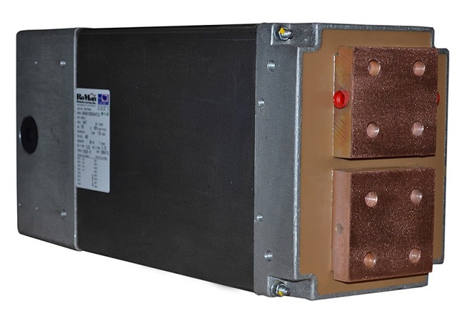
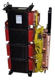
Machine transformers vary in size from small 20 KVA to large 500 KVA, AC units. These water cooled stacked core transformers are ideal for press, seam and rocker arm welders.
RWMA Size 3 Machine Transformer
These transformers frequently have tap switches to expand the power options.
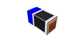
Fixture type transformers sometimes referred to as multiple spot transformer are used for multi-spot welding fixtures. These AC transformers run from 25 to 200 KVA. They can be built with outputs for either one or two secondary circuits. The secondary’s will fire together with the same power and settings sent from the weld control.
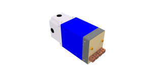
Fixture Type Transformer with two Secondary’s
Slope time can either be upslope or down slope as shown in the diagram below. Both are considered distinct segments of but part of the total weld time.
Upslope is a term to describe the beginning a weld cycle when the current is gradually increased from some lower value to a higher value over a period of time usually 3-10 cycles in standard AC welding. At the end of the upslope period then normally the full desired weld current is applied for the desired length of time.
Many transformers are manufactured with a core made by stacking sheets of magnetic permeable steal. This is common for large machine press welder transformers. This type of transformers can be manufactured into large transformers for a large application like 500 KVA.
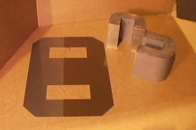
Typical Stacked and Wound Core Steel Transformer Components
Wound cores are used for robotic weld gun transformers. They allow for higher outputs with smaller weight and sizes.
The actual core material used for the transformers in these applications can vary by the transformer manufacturer and design. Contact the manufacturer for information on the material used in the core.
Machine Type Transformer
Reference: RWMA Resistacne Welding Manual, Chapter 19
Roman Manufacturing Inc.
The first step to identify a transformer is to look at the label on the transformer. Common North American transformers are labeled with part numbers:
AC – TXXXXXX
MFDC – TDCXXXXX
DC – DCXXXXX
If the label is not present then you could evaluate the transformer visually and electrically.
AC Transformers would have a 480V single phase input and a secondary single phase of 5- 24v, 60Hz output.
MFDC Transformers would have a 650V input @1000 Hz and an output of 5-24v at 1000 Hz.
DC will be three distinct transformers, one per phase. Each is substantially larger than an AC transformer. The input is 480V @ 60 Hz. The output is 5- 24v @ 60 Hz.
If you are not sure, take a picture of the product and send it to your supplier for help in identifying your transformer.
DC Transformer
Reference: RWMA Manual Chapter 19
Roman Manufacturing Inc.
Page 18 of 40
Have a Question?
Do you have a question that is not covered in our knowledgebase? Do you have questions regarding the above article? Click here to ask the professor.