
Controls & Transformers
Questions and Answers
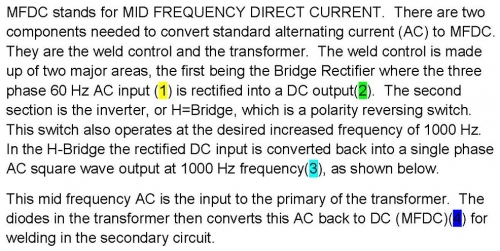
To calrify this issue attached is a previous article which shows the sequence of changes from the initial three phase 60 Hz AC input through several combinations of frequency and waveform changes to the final MFDC 1000 Hz output.
The ripple in the MFDC plot represents the 1000Hz frequency. The entire MFDC curve is on the positive side of the sine wave. MFDC does have a rise and decay of 3-8 milliseconds before and after full current is reached. This appears in the plot as an upslope or downslope. This should clear up the any questions. AN ARTICLE ON MFDC RISE AND DECAY IS ALSO AVAILABLE.
WHY or HOW DO MFDC CONTROLS CHANGE CURRENT FROM AC TO DC TO AC TO DC?
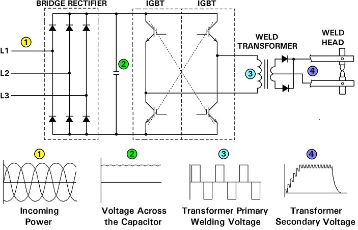
Schematic of Power Conversion In Control and Transformer of Mid Frequency Inverter
The advantage of MFDC is that the weld current has no zero cross overs so it heats the part quickly. Also, it is DC so there are no inductive power losses or problems with magnetic material in the machine throat.
Generally the plant power requirement is reduced substantially with the 3 phase input. Another advantage is robot payload. Higher frequency in the transformer allows the iron core to be smaller. This is a weight reduction which is significant on the end of a robot arm.
Reference: ENTRON Controls, LLC
In recent years MFDC has become the system of choice for new resistance welding machinery in North America. AC is widely used but for new equipment the preference is MFDC. Automotive and robotic lines use MFDC to take advantage of the weight savings not to mention power reductions and in house primary feed reductions, power factor improvements and others. MFDC does cost more and it is not forgiving if pushed beyond its rated limit.
Its electrical features are excellent in that it heats quickly and does not produce the sine way stitching with the zero cross over cooling. Since it is DC it has virtually no inductance loss when magnetic material enters the throat.
The electrical plot looks as shown below:
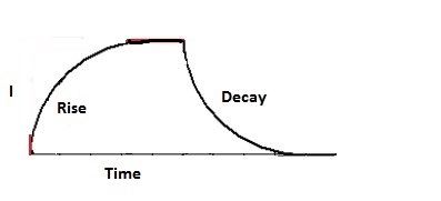
PLOT OF MFDC CURRENT
Depending upon the equipment the initial period from initiation of the current till the full current flow is reached takes 3-8 milliseconds (ms) in MFDC. This initial period is called “Rise Time”. When the power is turned off the same curve occurs and is called “Decay Time”.
For additional information about rise time and decay time see the article in this forum:
WHY IS THERE AN INITIAL UPSLOPE IN THE INITIAL CURRENT OF AN MFDC RESISTANCE WELDER?
Reference: RWMA – Resistance Welding Manual 4th Edition
AWS – Welding Journal, Q & A, July 2019
Hanging transformers are used with portable weld guns. They generally have long conductors to the guns. The transformers tend to be large to drive the power over these long cables.
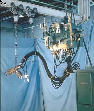
PORTABLE GUN & TRANSFORMER
The question is what type of core material is suitable for a hanging transformer. This is a machine design question and is beyond the scope of this forum.
Consult a transformer manufacturer for additional information.
Resistance welding transformer primaries are wound with many turns in order to produce the desired turns ratio. This in turn produces the conversion of the high voltage and low amperage in the primary to the desired low voltage and high amperage in the secondary. The winding material is copper and is required to conduct both current and heat at the amperage the transformer is designed for.
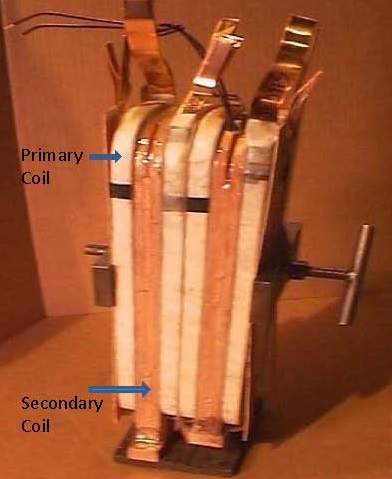
SUBASSEMBLY OF A TRANSFORMER
Calculation of the winding gauge size is a manufacturing question and is beyond the scope of this forum.
Contact a resistance welding transformer manufacturer for additional assistance.
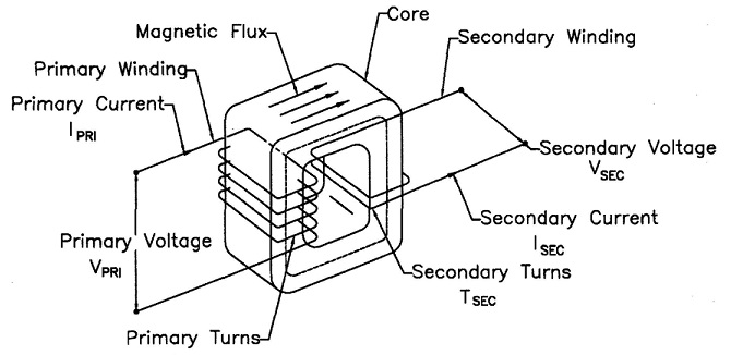
The turns ratio for all resistance welding transformers is calculated in the same manner no matter the KVA size. Turns ratio is the ratio of the number of coil turns in the primary vs the secondary.
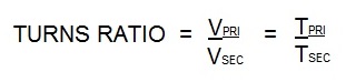
In AC transformers, there are many turns in the primary. The secondary has one turn. If there are 50 turns then the ratio is 50/1. Therefor the primary voltage will drop from 220 V and 100 amp input to 220/50 = 4.4 volts in the secondary. The equations for this are:
Vpri = Voltage on the primary Tpri = Turns in the primary coil
Vsec= Voltage on the secondary Tsec = Turns in the secondary coil
Power into the transformer will equal power out of the transformer.
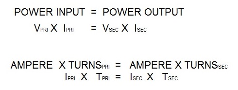
Isec = Secondary amperage
Ipri = Primary amperage
In the secondary using the above formula:
If the Ipri = 100 amperes
If the turns ratio = 50/1
Isec = (Ipri X Tpri)/ Tsec
Isec = 100 x 50/1
Isec = 5000 amperes
There are several additional articles written on turns ratio available in the “HOW TO RESISTANCE WELD” website. Enter “Turns Ratio” in the search box on the home page for additional information.
Reference: RWMA Manual Chapter 19
Page 13 of 40
Have a Question?
Do you have a question that is not covered in our knowledgebase? Do you have questions regarding the above article? Click here to ask the professor.