
Controls & Transformers
Questions and Answers
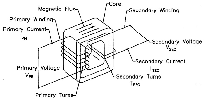
The transformer turns ratio in resistance welding reflects the number of secondary coil turns versus the number of primary coil turns. In AC transformers, there are many turns in the primary. The secondary has one turn. If there are 50 turns then the ratio is 50/1. Therefor the primary voltage will drop from 220 V and 100 amp input to 220/50 = 4.4 volts in the secondary. The equations for this are:
Duty cycle is a measurement of the % of the time that the transformer is conducting current during one minute. This value is used to insure that the electrical components are not operating above their thermal capability. Resistance welding transformers are rated at a 50% duty cycle. Each application may operate at different duty cycle up to and including 100% continuous.
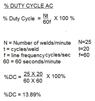
THE FORMULA TO CALCULATE DUTY CYCLE FOR AC is:
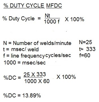
THE FORMULA TO CALCULATE DUTY CYCLE FOR MFDC is:
FOR MORE INFORMATION SEE ARTICLE:
Reference: RWMA Manual Chapter 19
Roman Manufacturing Inc.
Resistance welding transformers can have very high demand for a very short period of time. Installation of correctly sized primary conductors is imperative for the machine to run properly. The proper procedure to size these conductors for AC equipment is:
When the duty cycle of the machine is known
1. Calculate the duty cycle
2. Determine the weld current
3. Divide the weld current by the turns ratio of the weld transformer. This is the Primary Demand Current.
4. Multiply the Primary Demand Current by the square root of the duty cycle. This is the Primary Effective Continuous Thermal Current (ECTC).
5. Refer to the Ampacity Chart of the cable type to be used. Select the size based on the Primary Effective Continuous Thermal Current (ECTC).
If the Duty Cycle or Weld Current is not known or this is a general purpose machine:
1. Divide the transformer nameplate KVA by the primary voltage.
2. Multiply that result by the square root of 0.5 (RWMA transformers normally are rated at 50% Duty Cycle)
3. The result is the Primary Effective Continuous Thermal Current (ECTC).
4. Refer to the Ampacity Chart of the cable type to be used. Select the size based on the Primary Effective Continuous Thermal Current (ECTC).
Ampacity charts are based on the National Electric Code (NEC). There may be other state, local or company standards that must be followed.
Reference: National Electric Code
RWMA Manual Chapter -21.7
Roman Manufacturing Inc.
In many facilities it is beneficial to insure that the multiple welders in a station not fire at the same time to prevent a sudden large draw on the plant power supply. To spread this out cascade controls can be employed where one control will sequence through several contactors in sequence. The sequence and separation between the welds can be controlled to give an appropriate modest draw on the power supply.
Page 21 of 40
Have a Question?
Do you have a question that is not covered in our knowledgebase? Do you have questions regarding the above article? Click here to ask the professor.