
Controls & Transformers
Questions and Answers
The chiller is definitely the proper choice. It’s recirculating water will be routed directly into the internal secondary circuit conductors and the attachment pads on the transformer face. These components carry the high currents and are subject to the most heating.
A fan can only cool the outside transformer surface or cooling fins attached to the outside surface. This would be very inefficient and leave the internal secondary components subjects to heat buildup and possible failure.
Cooling water is critical for all major components of a resistance welder.
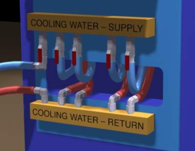
Water Manifold
City water or recirculating water from a water tower along with a chiller are acceptable for cooling a resistance welder and its components. All of the water systems are preferred over a fan since they will directly cool the desired component.
MFDC stands for MID FREQUENCY DIRECT CURRENT. Three phase AC @ 60 hertz input is converted to a high frequency 400-4000 Hz input to the transformer. The transformer then produces a DC output to the welder.
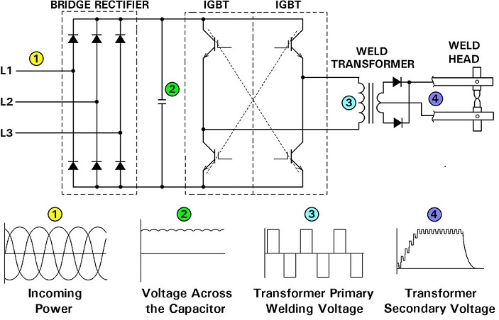
SCHEMATIC AND POWER CONVERSION IN CONTROL AND TRANSFORMER OF MID FREQUENCY INVERTER
AC stands for alternating current. Historically in North America the standard welding controls have been single phase AC @ 60 Hz input. The transformer produces a low voltage high amperage AC output at 60 Hz suitable to produce the desired welding parameters. The Typical AC sine wave outputs would look like those shown below.
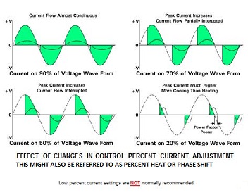
Each time the sine wave crosses zero the AC weld actually cools momentarily. Additional cooling occurs depending upon the amount of phase shift as shown above. As the heating accumulates the part heats up. AC equipment is very robust and can last a lifetime if properly cooled and operated within its rated capability.
MFDC is timed in milliseconds (ms). There are 16 ms in one 60 Hz AC sine wave. Because MFDC heats continuously, DC actually can produce the same amount of heat of one AC sine wave in much less time as demonstrated below:
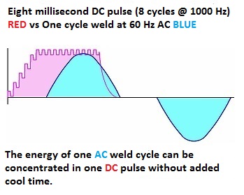
This attribute of heating without a zero cross over and no phase shift allows MFDC to heat quickly. Another feature is that inductive losses are nearly eliminated with DC. Therefor MFDC transformers can heat the parts with less power. Additionally MFDC transformers are operated at higher frequency’s which allows them to be made smaller. Smaller means less weight for a robot arm to carry.
MFDC has become the system of choice in the automation world. Timing in (ms) allows finer control of the process which can result in better process results.
Many applications are turning to MFDC because the process can:
Lower weight
It is fast
Reduce power requirements
Better resolution of heat control
The water itself would have some conductive properties but they should be very low as specified by AWS J1.2:2016. The machine, transformer and control should all be grounded. Therefore, the water does have a potential path to ground.
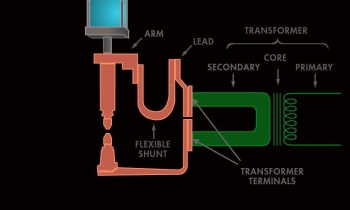
WELDER SCHEMATIC WITH COPPER CONDUCTORS
In the resistance welding process the secondary voltage is low, frequently 4-6 volts. With this low voltage the current is going to flow through the most conductive path. This is the copper and copper alloy conductors present in the form of conductors, shunts, cables and electrodes. The water potentially can conduct but is highly resistive relative to the copper conductors and very little conduction will be present. The water conduction will be minutely small in comparison to the thousands of amperes conducted through the copper system. This minimal flow pattern in the water is the same in AC or DC systems.
Reference: AWS J1.2M:2016, Section 4.5
Resistance Welding Manual, 4th Edition
A portable resistance welding gun was used frequently in the past but has seen less use with the introduction of the robot transgun. The portable gun is suspended from an overhead trolley by cables which carry most of the weight. The gun consists of the electrodes and force system. The portable gun transformer is located generally overhead and the power is transmitted by kickless cables (low impedance/water cooled) to the gun. These systems are still in use for respot/rework, remote robot and manual guns.
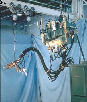
PORTABLE GUN & TRANSFORMER
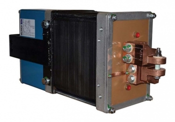
PORTABLE GUN TRANSFORMER
Transgun AC transformers are designed to be relatively light and compact with good power to fit on a robot arm for welding applications. These transformers vary in sizes from 35 KVA to 136 kva units (rated at 50% duty cycle). They are lightweight and designed for close couple mounting to welding guns. Their light weight makes them ideal for robotic applications.
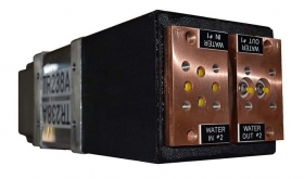
TRANSGUN TRANSFORMER
Page 15 of 40
Have a Question?
Do you have a question that is not covered in our knowledgebase? Do you have questions regarding the above article? Click here to ask the professor.