
Controls & Transformers
Questions and Answers
With MFDC and DC one generally considers the reactive impedance as very small in resistance welding. This is correct once the current is at steady state. Impedance is a combination of reactance and resistance in the welding circuit. In MFDC and DC the reactance during a weld is minimal as compared to a 60 Hz AC weld. However thare are still some effects of inductance that play a part in MFDC and DC resistance welding. Inductance is a property of a conductor that resists the change in current over time. In MFDC and DC this occurs at the beginning and end of a weld, when the current starts and stops flowing.
With MFDC and DC one generally considers the reactive impedance as very small in resistance welding. This is correct once the current is at steady state. Impedance is a combination of reactance and resistance in the welding circuit. In MFDC and DC the reactance during a weld is minimal as compared to a 60 Hz AC weld. However thare are still some effects of inductance that play a part in MFDC and DC resistance welding. Inductance is a property of a conductor that resists the change in current over time. This occurs at the beginning and end of a weld, when the current starts and stops flowing.
In the initial and final cycles when the current is changing, inductance does have an effect upon the process of MFDC. As the weld initiates the control measures the current each half cycle and realizes that it did not reach its desired current due to the inductance. The control will fire at full conduction during this time. This repeats until the desired current is reached. This is called rise time and is 3-8 milliseconds for MFDC. At this point the current is at steady state and the inductance goes to zero and the current levels off until the control turns the current off. When the control turns off, the inductive energy that was stored in the circuit will now bleed off. There will be a decreasing current flow until all is bled off. This is called decay time and is about 3-8 milliseconds.
DC equipment which operated at 60 HZ operates similarly but will have a different curve and take longer to reach steady state.
Plots of the output curves of both MFDC and DC will exhibit small ripples. These ripples reflect the electrical sine wave which has been rectified to 1000 HZ or 60 HZ.
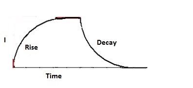
RED REPRESENTS NO INDUCTIVE LOSSES
BLACK SHOWS THE RISE AND DECAY RESULTING FROM
INDUCTIVE LOSSES
These inductive losses can be compared to a fly wheel. To get it started, extra energy must be put into the flywheel to get it turning, rise time. Once the target speed is reached no extra energy is required. It will continue at speed. When it is time to stop the energy of the spinning wheel must be removed to stop the wheel, decay time.
As discussed MFDC and DC will have different rise and decay curves.
Each welder potentially will have a different inductive load.
Reference: RWMA – Resistance Welding Manual 4th Edition
AWS – Welding Journal, Q & A, July 2019
This question describes a classic case of introducing magnetic material into the throat of an AC welder. As magnetic material enters the throat it causes the impedance to increase which absorbs energy and the weld current will decrease. This decreasing current will result in smaller weld nuggets. To counteract this one has the option of using a constant current control or use different schedules for the different welds. Impedance is not an issue for nonmagnetic materials or when using DC or MFDC welders.
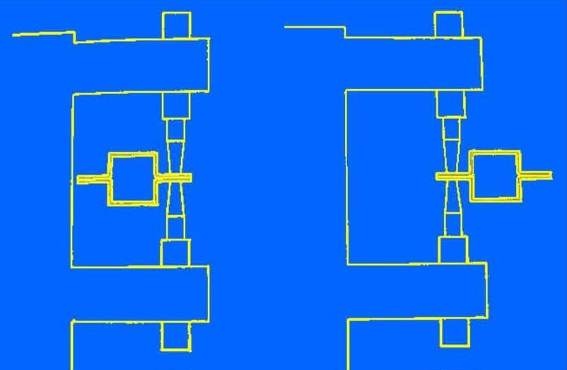
MAGNETIC METAL IN THE AC THROAT AREA INCREASES
IMPEDANCE WHICH WILL DECREASE CURRENT
All resistance welders consist of potentially four components that may require water cooling. They are the control, the transformer, the conductors and the electrodes with their copper holders. Machine or press welders have all of these components. Suspended hanging guns are similar but may use kickless cable for the conductors. Kickless cables are water cooled cables. Robotic applications generally use transguns which eliminate cooling the conductors but the mounting pads are cooled. In the case of seam welding, additional water may be sprayed directly on the workpiece and weld wheel at the weld zone to cool it down.
All cooling recommendations are for the machine and equipment longevity regardless of what material is being welded. In some specialty cases sensitivity to quenching of the workpiece might dictate a slower cool or special heat treatment. Slower cool can be obtained with a down slope at the end of the cycle. In other materials (i.e. Carbon content >0.4%) you may also need a Quench and Temper added to the weld schedule to maintain weld integrity.
Depending upon your system, an input and output water manifold would be assembled similar to the one shown below. The output and input water lines would be routed to the components that require water cooling. The plant water supply would be connected to the supply side of the manifold. This could be city water, plant water tower system or a chiller. The return would connect to a sewer drain, water tower return or chiller return.
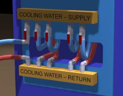
WATER MANIFOLD
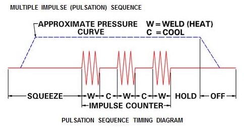
Weld pulses are frequently used to grow the size of weld nuggets without overheating the part. In most cases the pulses are a repeat of the initial weld sequence with a very short one or two cycle cool between sequences. The diagram below depicts this type of sequence.
Page 14 of 40
Have a Question?
Do you have a question that is not covered in our knowledgebase? Do you have questions regarding the above article? Click here to ask the professor.