
Controls & Transformers
Questions and Answers
A transformer has no moving parts. Yet it can convert voltage and current to different levels – HOW? In resistance welding high voltage/low amperage input are converted it into low voltage/high amperage output.
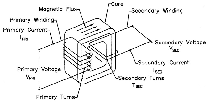
This conversion is made by winding two separate conductors around a common iron core. Applying an alternating voltage to the primary conductor produces current which sets up a magnetic field around itself. This is known as mutual inductance.
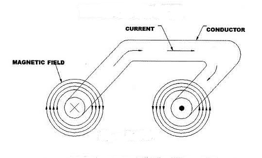
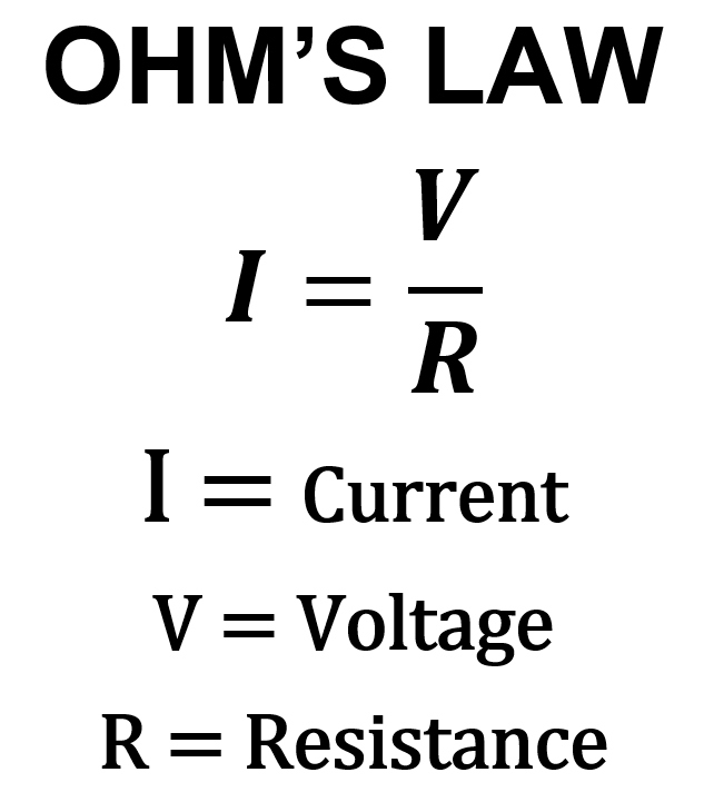
The magnetic field in the primary conductor creates lines of magnetic flux in the iron core. This magnetic flux in the core is what links the turns of the two windings. When the lines of the magnetic flux flow around the core, they pass through the turns of the secondary conductor inducing a voltage on the secondary winding. This secondary voltage is what produces the welding current based on Ohm’s Law.
In resistance welding the heat is generated according to Joules Law:
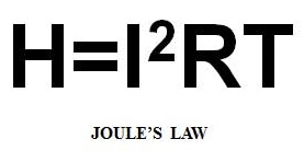
This dictates that relatively large currents will be passed through the weld joint to form the weld nugget. In order to do this economically and safely a transformer is used. The transformer’s function is to take a high voltage low amperage input and convert it into personnel safe low voltage high amperage output. The high amperage output is used to generate the heat defined in Joules Law.
After the math is worked out:
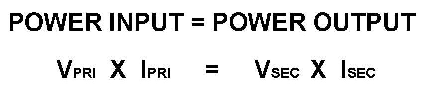
Primary voltage times the primary amperage will equal the secondary voltage times the secondary amperage.
Through this system the power company is able to economically deliver the high voltage/low amperage power for conversion by the transformer to low voltage/high amperage welding power.
The secondary reason to reduce the voltage is to make it safe for people to be around. The secondary voltage of the transformer generally runs from 2 – 25 volts. This is safe for personnel to be around in the secondary. Proper grounding of all machines is still required. The control has high voltage inside and should be restricted to authorized personnel.
It is the transformer that enables us to deliver safe high energy power to the resistance welder to make resistance welds.
Reference: RWMA Manual Chapter 19
AWS J1.2:2016
Roman Manufacturing Inc.
Impedance (Z) is the total opposition to current flow. It is made up of the Resistance (R) and Reactance (X).
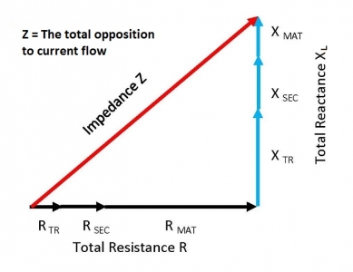
Reactance is created by the induced magnetic field around the conductors.
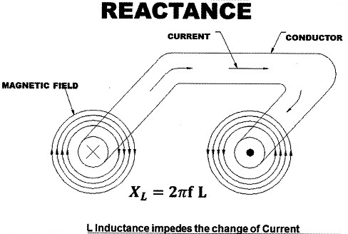
This induced field wants to stay in a steady state but in AC, current is constantly changing from positive to negative with the AC sine wave. The Reactance builds momentum in each half cycle and resists changing to the other direction. The stronger the magnetic field the larger the reactance (resistance). The size of the welder throat is a factor in determining this magnetic strength. Larger throat areas create stronger magnetic fields.
Ohm’s Law defines current as:
I= E/R
Where I is the current in Amperes, E is the potential in Volts and R is the resistance in Ohms.
In alternating current this formula becomes
I= E/Z
Where Z is impedance measured in Ohms.
(Z) Impedance has two components. They are R (resistance) and X (reactance).
The reactance of the secondary AC circuit is subject to changes in throat welder size and proximity of any magnetic materials. Therefore welder throat size is a factor in welder performance.
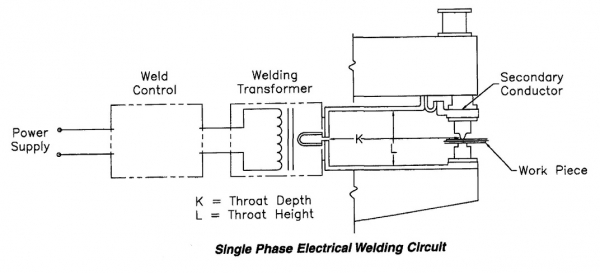
Larger throat sizes (K or L) increases the reactance and therefore the impedance increases. By Ohm’ Law the current will decrease with larger throat sizes.
Page 19 of 40
Have a Question?
Do you have a question that is not covered in our knowledgebase? Do you have questions regarding the above article? Click here to ask the professor.