
Spot Welding
Questions and Answers
Yes, a flat backup bar could be used to reduce indentation on the one side. It may be more prudent to use a large flat faced electrode on the side you would like to reduce indentations. A flat faced “C” nose electrode of the same body diameter as the electrode on the other side of the weld is commonly used. A larger diameter could also be used, for example a #5 flat face opposite a #4 pointed “A” nose. Of course if the tooling arrangement is easier to use a backup copper chrome (Class 2) bar that can accomplish the same goal.
Flat electrode or bar, the goal is to spread the heat on the good/no mark side of the part out over a large area. Using a smaller face on the other side will concentrate the heat on that half of the part. The nugget should form mostly on the non-show side of the part. Permit the weld nugget to grow into the good side only enough to make an acceptable weld. We are describing what is called a cosmetic weld.
It is possible to use carbon dioxide (CO2) in place of nitrogen atmosphere. Before making the substitution several issues should be considered. Nitrogen is considered an inert atmosphere. It does not react with any other gases present. It displaces them. Nitrogen is a good choice as long as the purge is sufficient to completely remove all other gas products. Carbon dioxide (CO2) is a good more reactive, protective gas. It displaces other gases but can also react with any remaining undesired products. The negative is that CO2 could react during the welding process. The CO2 in the presence of the weld energy might break down. Oxygen would be generated and that could lead to oxidation/discoloration of the TO-39 package.
If a shop is currently joining steel and stainless steel components, depending on the design and part specifications, spot welds can be successfully used. To do this the part design must be such to alloy room for the spot welds in sufficient quantity, size and location to meet the specified strength requirements. The materials being welded must also be of sufficient strength, thickness and stack up or combination of to have the proper resultant spot weld strength.
There are instances where there is insufficient space to design a flange for the desired number or size of spot welds. In these cases the spot weld might be used as a locator and a MIG weld might be used to add sufficient strength to the joint.
Aluminum is a very conductive material. Therefore we know that it has a low resistance. If we look at Joules Law:
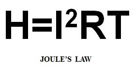
To generate heat, if the resistance is small the heat will have to come from either more current or time. In general numbers, low carbon steel will resistance welds at 10,000 amps. Aluminum resistance welds at 35,000 amps. This is a very high current for the electrode material to conduct. Therefor you would always select the most conductive copper alloy available. Class 1 is the material of choice for welding aluminum. Class 1 is a Copper Zirconium alloy. Its Alloy ID is C15000.
Standard full size electrode designs are specified by the Resistance Welding Manufacturing Alliance – RWMA. These designs can be found in the RWMA Resistance Welding Manual. The RWMA standard sizes are #4, #5, #6 and #7. These sizes represent full size electrodes with body dimensions of 1/2”, 5/8”, 3/4” and 7/8” diameter respectively. These electrodes can be purchased in RWMA Class 1, 2 or 3 materials. RWMA face configurations A, B, C, D, E and F are standard. Full size electrodes are stocked in sizes 4, 5, & 6 in most Classes of material and nose designs. Size 7 is available is some configurations. Full size electrodes are available in overall lengths from 1to 4”.
Page 30 of 44
Have a Question?
Do you have a question that is not covered in our knowledgebase? Do you have questions regarding the above article? Click here to ask the professor.