
Seam Welding
Questions and Answers
Metal pickup on the wheels can definitely change the welding parameters at the welding interface. The geometry of the weld face has changed and the contact resistance has changed. Both will have a large affect upon the heat at the weld interface. Many machines have knurled welding wheels. The knurl can maintain a constant fresh geometry and face condition by continually recutting the seam weld wheel as it rotates.
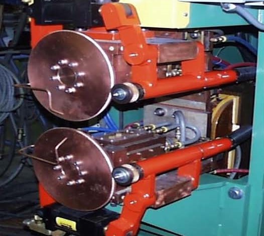
KNURL DRIVEN WHEELS
An additional issue to consider is proper force maintenance. AWS Standard C1.1 Table 3 calls for 900 lbs force on the part for 0.79 mm (0.031 in) material. This is not the air pressure supply but force on the part. This can be calculated based on the supply psi gauge and calculate using the size of the machine cylinder. The other option is to use a force gauge to measure the force between the wheels.
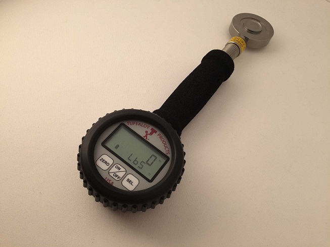
FORCE GAUGE
Another factor which cannot be overlooked is that heat could build up after welding several parts. Check the machine cooling system to insure it is functioning properly. If cooling at the wheel face and part interface is a problem that other remedies cannot solve, Flood cooling is always an option.
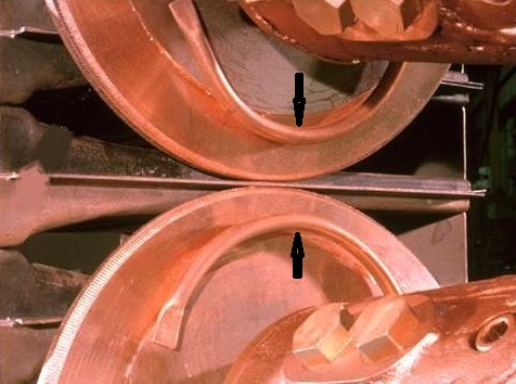
ARROW INDICATES FLOOD WATER TUBES
Reference: RWMA – Resistance Welding Manual Section 4
AWS C1.1 Recommended Practices for Resistance Welding
Seam welding is a power intensive process. Especially with a fuel tank which must be leak proof. The welds must overlap the full perimeter of the tank. Depending upon the material and its thickness the power will vary. Consequently, the weld schedule and heat will vary.
In some applications flood water cooling may not be necessary. In other applications flood water cooling will be necessary. The amount of water desired for flood cooling could vary greatly from one liter/minute to many liters/gallons of water/minute.
• Yes, there will be evaporation but it likely will be minimal compared to the water flow.
• Yes, one should try to avoid getting water into the fuel tank.
• The cooling flood water can be recirculated and reused if prevented from building up too much heat.
• Make up water may be necessary to cover losses and evaproation.
SEAM WELDER WITH FLOOD COOLING
Every application is different and every product has its own specifications to build to. This dictates the seam welding schedule and how much cooling will be required. The specification cannot be offered from this blog.
References: RWMA – RWMA Resistance Welding Manual 4th Edition
A seam welder has the same components as any other resistance welder. They require the same water cooling as all resistance welders. Water or other similar fluid is a must to perform the cooling of these critical machine components. These components are:
• Transformer
• Conductors
• Control
• Electrodes
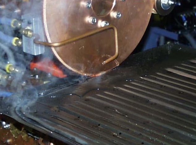
In the case of the seam welder the electrode is a seam welding wheel water cooled at the central hub. Some applications generate excessive heat at the weld area and demand the use of external flood cooling directly at the weld joint.
ARROWS INDICATE EXTERNAL FLOOD COOLING TUBES
The question raised is: Can compressed air be substituted for water?
Water as compared to air at a minimum is fifty times more heat conductive than air. For the machine components it is doubtful that a machine manufacturer would warrant a machine cooled with air. Water must be used for the machine.
If a part producer chooses to externally cool the wheel weld face and part with air, that is up to the producer and his customer and the quality specifications required. Many parts are not externally cooled. It depends upon the amount of heat generated. Air may work?
Water flood cooling is messy but it works.
FOR ADDITIONAL INFORMATION REFER TO OTHER ARTICLES IN THIS BLOG:
“WHAT IS THE PROPER AMOUNT OF WATER COOLING FOR SEAM WELDING?”
“IS THE WATER USED FOR SEAM WELDING HARMFUL AFTER BEING USED FOR COOLING?”
References: RWMA- RWMA Resistance Welding Manual 4th Edition
AWS- AWS Standard J1.2 Guide to the Installation and Maintenance of Resistance Welding Machines
Seam welding can generate large amounts of heat. Especially when making a liquid tight continuous weld. This heat is very visible at the actual weld joint. You stated that you are using cooling water as specified by the machine manufacturer at 20 l per minute. This may be adequate for the machine under normal operation. It does not mean that at the weld area the cooling is adequate.
Heat can be a suspect to address. The machine produces good welds for 300 meters. Then cracks appear. After stopping for a period of time the machine is cooled down. A restart produces good product for another 300 meters. If the hub cooling of the wheel cannot adequately cool the wheel to keep the wheel rim face at a steady heat condition, the rim face heat will build up and gradually get hotter. The part will not cool as quickly and the process will change. Apparently, CRACKING results.
Cooling of the part/wheel weld area with external direct water flood cooling as shown below is one option. This is messy but functional. The general rule of thumb is a flow rate of 4-6 l per minute.
ARROWS INDICATE FLOOD WATER TUBES
The other option is to attach a water cooling chamber on one face of the wheel. Use “O” rings to seal the water in and flood the chamber with water to near the weld face.
Is the Wheel rim face condition an issue?
• Is the wheel being faced/dressed during use?
• Does it build up and get rough and cause the cracks due to no dressing?
• When the machine stops do the wheels get dressed and produce good product until they get rough again?
Since heat is an issue one has to address the issue of the machine duty cycle. Is the machine operating safely at less than the normally rated 50% maximum duty cycle?
Several articles in this blog address Duty Cycle including:
HOW DO YOU CALCULATE DUTY CYCLE?
If the machine is nearing the 50% value then additional water cooling may be required. Cooling towers or Chillers may be needed.
Reference: RWMA – Resistance Welding Manual Section 4
Weld schedules are available the Resistance Welding Manual and AWS Standard C1.1 for many of the most frequently used materials. The information commonly provided is the proper electrode design, size and material. The weld force, weld time and weld current are also published. The minimum distance between welds if usually listed and the expected nugget or button size is shown. Tensile properties frequently are also published.
All of this is good information to use as a starting point. Each application will dictate some variation from these settings. These numbers will act as a good guide or goal for your application.
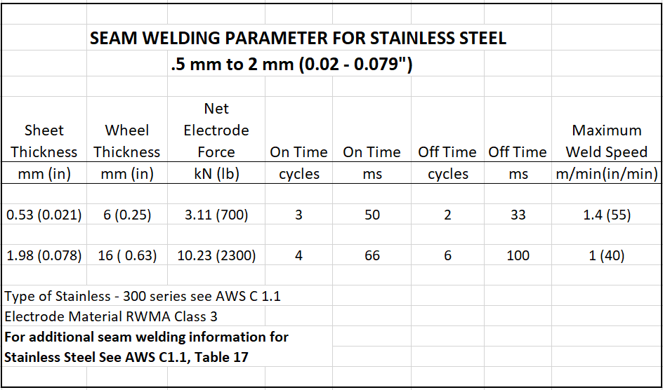
I suggest a purchase of a copy of AWS Standard C1.1. It has a complete set of data that you can use for initial set up. Then fine tune for your machine, product being welded and desired results.
References: AWS C1.1 Recommended Practices for Resistance Welding
RWMA – RWMA Resistance Welding Manual 4th Edition
Page 1 of 11
Have a Question?
Do you have a question that is not covered in our knowledgebase? Do you have questions regarding the above article? Click here to ask the professor.