
Spot Welding
Questions and Answers
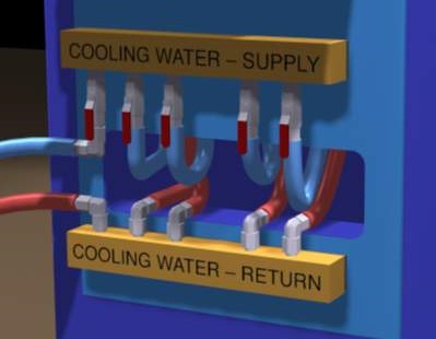
Many components in a resistance welding machine should see 4-6 L per minute (1-1.5 gal/min) of water. This is a very high necessary flow of cool water. The specifications for this water can be found in:
AWS Specification AWS J1.2 Guide to Installation and Maintenance of Resistance Welding Machines
Proper sizing of the electric, air and water for a welder installation is very important. It should be done by professionals. The machine manufacturer may provide specifications for the installation. Contact local qualified installers.
This subject is beyond the scope of the blog.
Reference: American Welding Society - AWS J1.2 Guide to Installation and Maintenance of Resistance Welding Machines
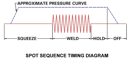
An inquiry came in after reading about PCT, It asked when does current flow? To clarify current flows during weld time. Be it AC, DC or MFDC equipment. Weld time is when the current is ON. The current is on the length of time T of PCT. The amplitude of the current is C of PCT. By now you know that the pressure or force is P of PCT.
To see and understand this better please view another article in this blog:
HOW ARE PRESSURE CURRENT AND TIME USED IN RESISTANCE WELDING?
Reference: RWMA Resistance Welding Manual 4th Edition
The answer is yes. One could, but it is not recommended. Stainless requires relatively high forces and pure copper without alloy strengthening additives does not have the strength at the temperature generated to hold up. Mushrooming will occur quickly. Weld nugget failure will be frequent and require constant electrode dressing and attention.
My answer is no don’t use pure copper. In another blog article electrode selection for stainless steel was addressed:
WHAT IS THE PROPER ELECTRODE MATERIAL FOR SPOT WELDING STAINLESS STEEL?
Stainless Steel weld schedules are available in:
AWS Specification C1.1 Recommended Practices for Resistance Welding
In this specification the data necessary to dial in a good starting weld schedule is available
Reference: AWS Specification C1.1 Recommended Practices for Resistance Welding
RWMA Resistance Welding Manual 4th Edition
Job shops continue to have foot operated resistance welders in use. They are fewer but they are out there. The operators foot actually provides the initiation and force of the weld with leverage multipliers built into the machine design. To replace the persons foot a force mechanism must be provided. It must be capable of providing the force needed for the application.
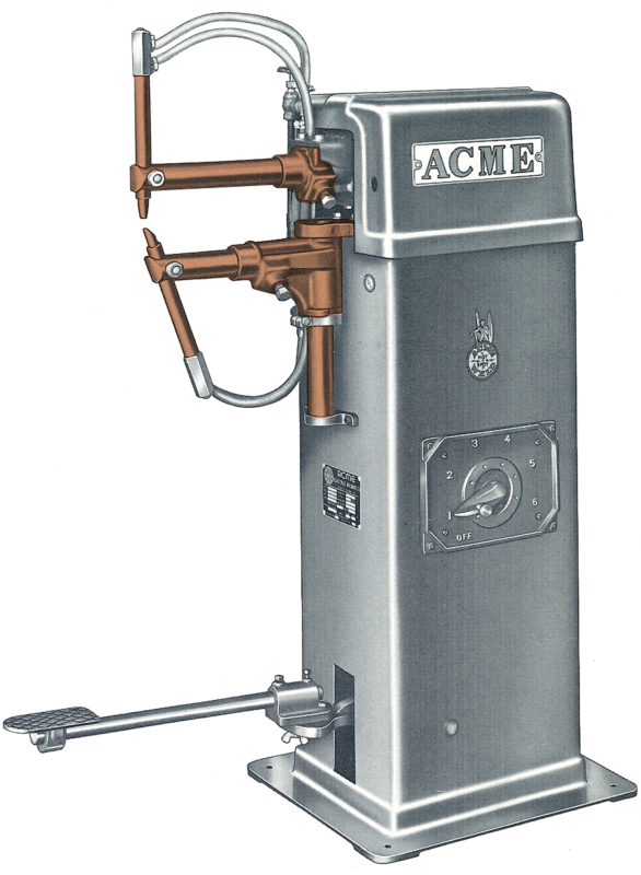
FOOT OPERATED ROCKER ARM WELDER
To spot weld 1 mm (0.040 in) or 3 mm (0.120 in) steel a force of 3 Kn (700 lb) to 4.5 Kn (1000 lb) approximately might be used. A pneumatic cylinder which could produce that strength through the mechanical advantages built into the machine would be necessary. Stroke length would also need to be considered. These and other considerations can be discussed with local area Resistance Welding Machine Suppliers or Distributors. They will know the proper sources for the parts and information to make this conversion a success.
Machine design is beyond the scope of this discussion.
During nugget solidification the metal shrinks in volume and gases can be released at the same time. As this happens it is important that the part is held together under good pressure to prevent the joint from separating and failing but also to minimize voids. This is the hold time in the weld schedule. The force mechanism of the welder must be in good repair in order to be able to maintain constant force and follow-up as the material solidifies and shrinks. This is especially true with projection welds where the projections collapse.
The parameters to maintain for void reduction are:
Hold Time
Pressure Mechanism Maintenance and application
Forge application
Hold Time
Make sure there is hold time. Some schedules don’t allow hold time because it slows down the production rate. Hold is necessary to insure the faying surfaces are together until the nugget is solidified. In some applications it is used for void closure and forging or tempering.
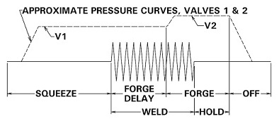
FORGE DELAY
Force is increased as the weld ends to forge the metal as it is solidifying to close voids. This is very prevalent with aluminum.
Pressure Mechanism Maintenance and Application
It is imperative that the pressure force system of the machine be in good working order. Be it cylinders or servo they must react when needed immediately with no delay or catches in their movement. Their ability to have good follow-up is important. This means they must move as the weld expands and contracts. This can be very fast. Remember welds are measured in cycles and milliseconds not seconds. A cylinder or servo that sticks is not acceptable.
Forge Application
The application of extra pressure or force during the solidification process is a very good tool to reduce voids. It essentially closes gas pockets and forges voids together. As shown in the figure above you may have to initiate this during the end of the weld cycle. Mechanical functions don’t react as quickly as electronic functions. This may take a little trial and error. If you squeeze too hard too soon the molten metal can be pushed out of the joint. Force may be the most important function to eliminate voids.
Reference: RWMA – RWMA Resistance Welding Manual 4th Edition
Page 7 of 44
Have a Question?
Do you have a question that is not covered in our knowledgebase? Do you have questions regarding the above article? Click here to ask the professor.