
Spot Welding
Questions and Answers
Weld is the second of the three main resistance welding functions. They are squeeze, weld and hold. During Squeeze the proper pressure builds up prior to current initiation. Weld is the period when the current flows and the weld nugget is formed. The Hold period marks the end of weld current and the beginning of the weld cooling and solidification under pressure.
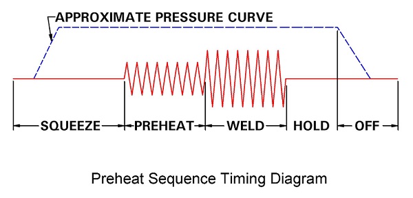
The amplitude and time of current flow is critical to forming the proper size nugget. The weld control controls the weld function and is able to accurately repeat exactly the same process each weld cycle for each part.
Reference: RWMA – Resistance Welding Manual 4th Edition
The number and spacing of spot welds will depend upon many factors. The material being welded for example – steel or aluminum. What type of part is being welded – a hair dryer or an automobile? Is the weld a structural weld? Is it a considered a safety weld? Shunting current must be avoided between welds that are too close together.
Reference Article: IS THERE A MINIMUM SPACING BETWEEN SPOT WELDS?
These and many other factors are considered by design engineers when they specify the number and location of spot welds. A full discussion of this topic is beyond the scope of this blog.
Reference: RWMA Resistance Welding Manual 4th Edition
Hastelloy X is a high temperature Nickel bearing alloy frequently used in the aerospace industry. It is readily weldable by Gas Tungsten Arc Welding (GTAW), Gas Metal Arc Welding (GMAW), Shielded Metal Arc Welding ( SMAW), and Resistance Welding (RW).
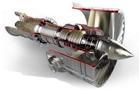
HASTELLOY X - AIRCRAFT APPLICATION
The recommended material preparation for welding HASTELLOY x is the same as for all resistance welding. The weld area and adjacent areas should be cleaned of all oil, grease, cutting oils, debris, scale, paint, markers and all foreign matter. Any appropriate solvent may be employed. There is no published standard for cleaning this material.
Reference: Haynes International – Hastelloy X
RWMA – Resistance Welding Manual 4th Edition
Machine qualification, building and design are out of the scope of this blog.
For information on machine qualification consult a machine builder or distributor.
Reference: RWMA – Resistance Welding Manual 4th edition
AWS - J1.2, Guide to the Installation and Maintenance of Resistance Welding Machines
Aluminum is a soft low resistance material. Additionally, it readily forms nonconductive oxides on its surface very quickly. Due to its low resistance high currents are required 30-40,000 amperes. As compared to steel at 10,000 amperes. It melts at low temperatures and has a high coefficient of expansion. Care must be taken to maintain force as the nugget shrinks (fast follow-up) (secondary forge cycle) or voids will be present.
To address sticking, it melts at low temperatures. It requires high currents. High currents through the electrode mean heat and could lead to electrode face pickup and sticking. This must be minimized. Use the most conductive electrode alloy RWMA Class 1. Use a radius face to concentrate the current in a small area for affect. This helps to break through any remaining surface oxides not removed in the recommended aluminum surface cleaning. Additionally the weld should be hot but short. Just a few cycles if AC and a few millisecs if MFDC. The point is to minimize the time of the weld and keep the electrode face cool. The cooler it is the less pick up there will be. Internal water cooling of the electrode is always a requirement.
What I have described is outlined in AWS standard:
AWS C1.1 Recommended Practices for Resistance Welding
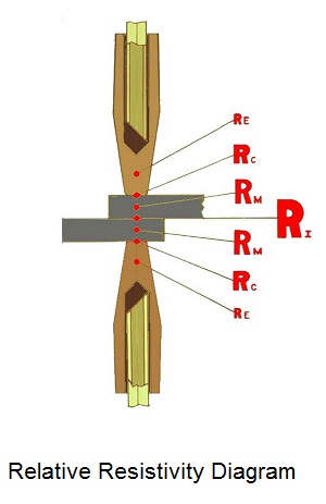
The need is to deliver the proper current but keep the contact resistance low RC
Reference: AWS C1.1 Recommended Practices for Resistance Welding
RWMA Resistance Welding Manual 4th Edition
Page 5 of 44
Have a Question?
Do you have a question that is not covered in our knowledgebase? Do you have questions regarding the above article? Click here to ask the professor.