
Projection Welding
Questions and Answers
As stated in several articles millions of weld nuts and bolts are welded every month probably each week. The industries include automobiles, aircraft, appliances, office furniture, appliances and many others. Their function can be very critical dependent upon the application. Assorted projection welding nuts are shown below.
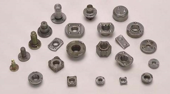
ASSORTED WELD NUTS
The quality of these projection welds is very important. They are tested for torque, push off and set down.
In this blog there are three articles that discuss the status of testing:
WHAT ARE THE QUALITY STANDARDS FOR NUT PROJECTION WELDING?
WHAT VARIATION IS EXPECTED IN THE PUSH-OFF TEST OF A PROJECTION WELDED NUT?
IS THERE A WELD STANDARD FOR WELD NUT SET DOWN?
The conclusion of these articles is that at this time there are no published strength or test standards available for projection nut or bolt evaluation.
The articles do offer guidelines to develop values that can be used in many applications.
References: AWS Welding Journal: January & March 2011 Q & A “Quality of Forged Projection Weld Nuts” by DONALD F. MAATZ JR.
AWS C1.1 Recommended Practices for Resistance Welding
Attaching weld nuts is a projection weld due to the design of the weld nut. An attempt to direct power from a single transformer to three weld nuts at once and maintain a balanced current to all three would be difficult.
If one wanted to use one transformer to make multiple welds a cascade arrangement would be a better set up. Here the transformer is attached to all three weld guns. The weld control is a cascade arrangement that allows only one gun at a time to close and have current flow.
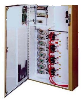
FOUR CASCADE CONTROL
In the above control four cascade welds can be programed independently. Each weld would made independently in sequence. This reduces demand on the buss and the transformer since this is four individual welds not four at one time.
Reference: RWMA Resistance Welding Manual 4th Edition
Cross wire welding is a form of projection welding. When two wires are crossed that is a point contact. The heat and force are concentrated at that point contact. Even welding a wire to a sheet is a projection weld concentrated in a line point contact. Weld schedules are available in the literature for this type of operation.
There is an article in this blog on this subject which answers this question:
WHAT SCHEDULE SHOULD BE USED TO CROSS WIRE WELD 9 GAGE LOW CARBON GALVANIZED STEEL WIRE?
This article offers an example of the data that is available in AWS Specification C1.1 for weld schedule set up. Force, current and time are shown as starting points. The data will not cover all circumstances but does offer enough information that one can develop a starting point for most circumstances including bare versus coated materials.
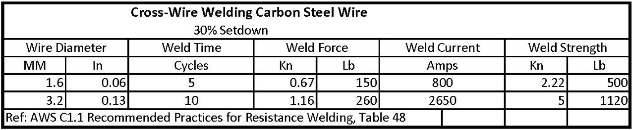
Electrode alloy selection is generally RWMA Class 2 or 3. The choice depends upon wear. Normally a flat face is used but a grove to match the wire is sometimes incorporated. The flat face will eventually have a groove wear in. The electrode face size is usually large so the current flows into a large surface area of the part. One is not trying to create heat at this interface.
Every machine and set up is different and the actual set up schedule will vary from the book values. Use the values tabulated as a guide. Start at low power values to avoid dangerous expulsion. Gradually increase the time or power with caution until the desire weld is accomplished. Expect coated materials to require a higher current level than bare material and they may exhibit more expulsion.
Reference: AWS: AWS Standard C1.1 Recommended Practices for Resistance Welding
RWMA: Resistance Welding Manual 4th Edition
This answer has been partially answered in a previous article for a 6 mm weld nut. The 8 mm weld nut would weld with similar values. The data can be found in the same referenced source. The question did not specify the weld material so an exact answer cannot be given.
The referenced article is:
WHAT IS A STARTING WELD SCHEDULE FOR A FOUR PROJECTION M6 WELD NUT TO 3 MM (0.117”) STEEL?
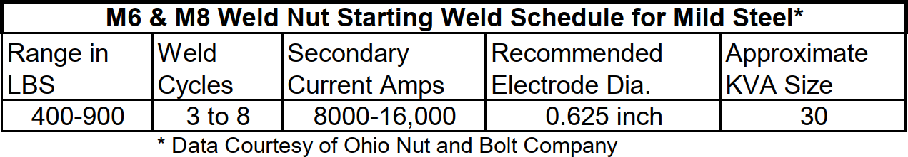
The Ohio Nut and Bolt Company website is a good source for projection nut welding data.
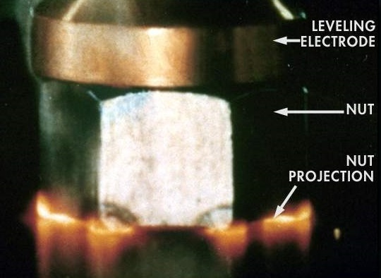
WELD NUT BEING WELDED
Use the above data and develop the proper settings for your application.
When setting up a new schedule always start with low power settings to avoid unexpected expulsion.
References: The Ohio Nut and Bolt Company
RWMA – Resistance Welding Manual 4th Edition
AWS Standard C1.1 Recommended Practices for Resistance Welding
Tapered electrodes are the most used system for attaching electrodes to their holders/tooling in spot welding. Tapers are frequently used in projection welding for attachment. The ease of changing electrodes is the reason for this. As long as the electrode can be removed by a simple twist of the removal tool tapers are the best choice.
This chart indicates the proper taper/electrode size or thread vs force.
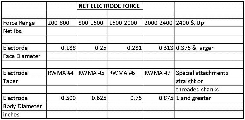
As the duty cycle or demand of the application goes up – force and heat. This my change and other attachments become better choices. The chart above shows that at 2400 pounds force tapered electrodes must be replaced with threaded or flanged electrode designs. Nut welding is a large user of threaded faced electrodes with locator pins. The forces, and heat make the tapered electrode not a good choice in many of heavy-duty nut weld applications. The threaded electrodes are easy to remove and refurbish and replace as desired. Tapered electrodes are used for nut welding but it comes down to how much heat and force they see. How often will the electrode need to be removed and how difficult will it be. If it only needs to be changed once a week that is great but if it won’t come out of the tooling ??? You have lost the entire fixture. Choose the tapered, threaded or flanged electrode system that can be removed with less difficulty.
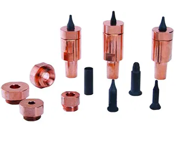
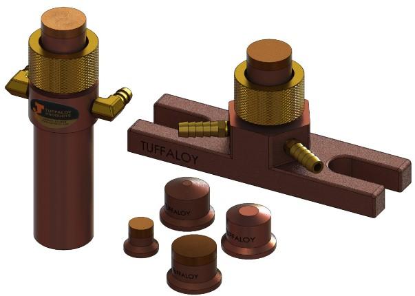
TAPERED NUT ELECTRODES THREADED WELD NUT FLANGED WELD SYTEM
All three systems can be alloy copper faced or copper/tungsten faced, with or without locator pins.
This discussion applies to more than nut welding. It can also apply to any projection welding if electrode wear and changing becomes an issue.
Contact your local welding distributor for advice in making the proper system choice.
Reference: RWMA Resistance Welding Manual 4th Edition
Tuffaloy Resistance Welding Products Catalog
Page 3 of 14
Have a Question?
Do you have a question that is not covered in our knowledgebase? Do you have questions regarding the above article? Click here to ask the professor.