
Controls & Transformers
Questions and Answers
In resistance welding there is opposition to current flow. This is especially true in AC welding systems. The total opposition to current flow is IMPEDANCE. Impedance is made up of two components resistance and reactance.
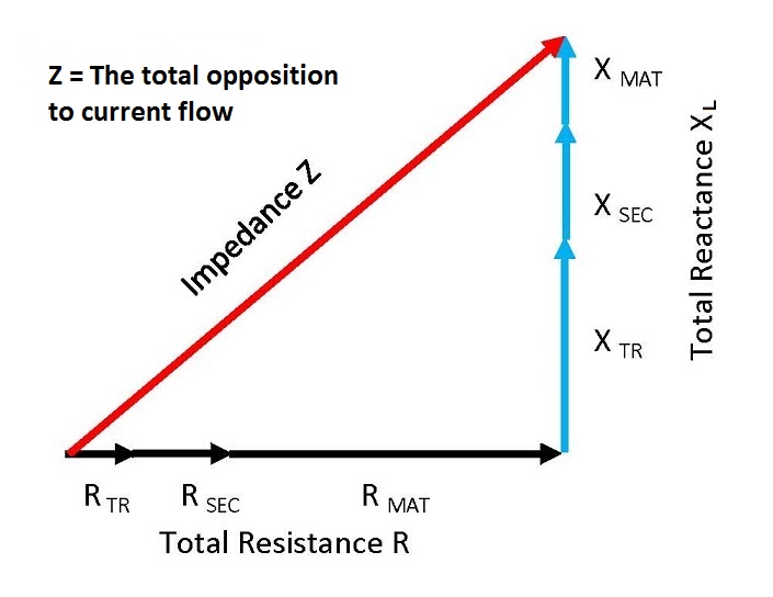
Reactance (X) is basically only present in AC circuits.
Reactance (X) is created by the induced magnetic field around the conductors in the secondary.
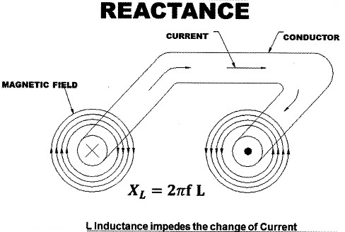
This induced field wants to stay in a steady state but in AC, current is constantly changing (reversing from positive to negative) with the AC sine wave. The Reactance builds momentum in each half cycle and resists changing to the other direction. The stronger the magnetic field the larger the reactance. The size of the welder throat is a factor in determining this magnetic strength. Larger throat areas create stronger magnetic fields.
This question gets into the design of machine components. Design is beyond the scope of this blog. An article has been written in this blog which describes the components of an MFDC system:
“WHAT IS MFDC WELDING?”
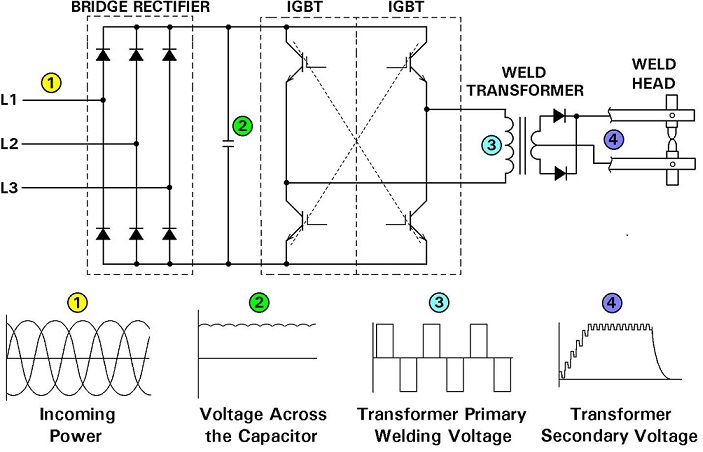
Schematic Power Conversion In Control and Transformer of Mid Frequency Inverter
Reference: RWMA Resistance Welding Manual 4th Edition
The model number identifies this as a 120v/60Hz transformer. Contact a local distributor or manufacturer. They will be able to help identify your transformer.
Design and building of specific equipment is beyond the scope of this blog.
A transformer for a machine/press welder is shown below.
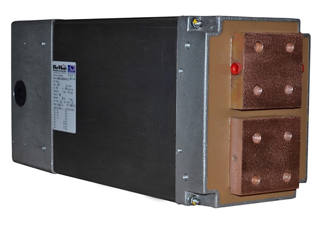
MACHINE TRANSFORMER
Reference: RWMA Resistance Welding Manual 4th Edition
This answer to this question is in another article published in this blog copied in full below:
“HOW DOES A TRANSFORMER CONVERT VOLTAGE AND CURRENT?”
The direct hot-pressing technique of powder materials is referred to as field assisted sintering. In this case resistance heating through the green pressed graphite part would generate the heat. The combination of heat and pressure would generate the desired final properties in the finished graphite product.
The heat is generated per Joules Law:
Yes, MFDC can be used to generate the heat for hot pressing.
Page 11 of 40
Have a Question?
Do you have a question that is not covered in our knowledgebase? Do you have questions regarding the above article? Click here to ask the professor.