
Projection Welding
Questions and Answers
Assorted projection welding nuts are shown below. They are being welded in industry every day for cars, appliances, office equipment and many other products. Proper welding is imperative since many important items are being fastened to these nuts.
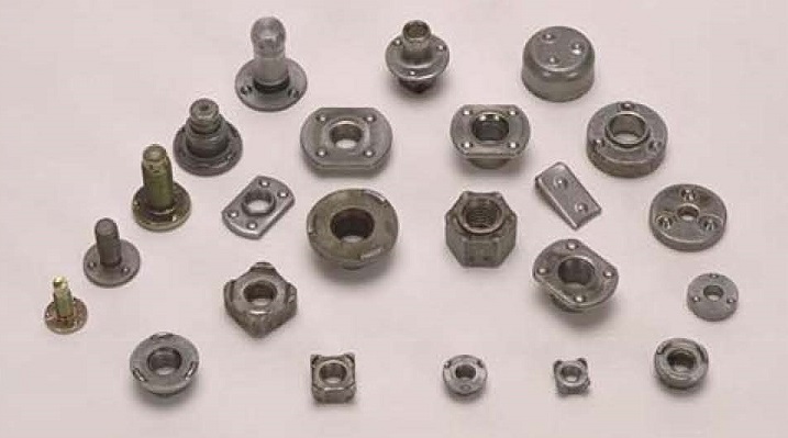
ASSORTED WELD NUTS
There is very little published data available on the subject of nut welding fasteners. A few articles have been written. Some data is available on the website of fastener manufacturers.
Two articles can be found in:
WELDING JOURNAL: RWMA Q & A JANUARY & MARCH 2011 – “QUALITY OF FORGED PROJECTION WELD NUTS”
This could be rephrased to be - What are the parameters of a projection welding process? In this case what parameters should be checked besides pressure, current and time when projection welding (PCT)? Before we move on, these three cannot be passed over. If the control or force application is not functioning properly the projection weld will not meet specification. The appropriate components must be part of the regular preventive maintenance list and checked daily, weekly, monthly as prescribed. A guide to machine and equipment maintenance can be found in:
AWS J1.2 GUIDE TO INSTALLATION AND MAINTENANCE OF RESISTANCE WELDIGN MACHINES
The first step in developing a process is to know what is to be welded. What is the material, it’s temper, coating, thickness and cleanliness. The number of welds. Where and the quality requirements.
Now let’s look at the equipment to be used for the job. Several machine set up items must be addressed before the schedule is developed. In projection welding normally several projections or even a full ring projection are being welded at the same time. For this to occur successfully the tooling and machine have to be set up properly and operating efficiently. Important factors are:
FORCE APPLICATION AND FOLLOW-UP
ALIGNMENT
PROJECTION SHAPE, SIZE & CONSISTENCY
ELECTRODE MATERIAL AND CONFIGURATION
FORCE APPLICATION AND FOLLOW-UP: The force must be applied perpendicular to the plane of the weld faying surface. A rocker arm which welds with an arc motion is not appropriate for projection welding. Straight acting press welders, table mounted weld guns with suitable force will do. The source of the force must be consistent and fast. The servo or cylinder must move smoothly with no hesitation. Fast follow up refers to the ability to maintain full force as the projection begins to collapse. If the machine does not maintain/follow up with full force at the moment the nugget begins to collapse and could be solidifying the weld strength will be compromised. Low inertia cylinders, machines and servos are manufactured for this purpose. Low inertia holders are also available to retro fit slower machines. This is a case for periodic preventive maintenance to insure that a cylinder, servo is always in good working order and not starting to hang up.
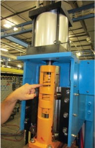
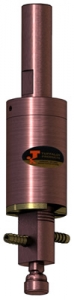
LOW INERTIA WELDER FAST FOLLOWUP HOLDER
The first step in developing a process is to know what is to be welded. In this case we are using stainless steel. From this we know that we have a strong, resistive material. Depending upon the material grade it could be subject to embrittlement, if it cools too quickly.
Let’s not get ahead of ourselves. Several machine set up items must be addressed before the schedule is developed. In projection welding normally several projections or even a full ring projection are being welded at the same time. For this to occur successfully the tooling and machine have to be set up properly and operating efficiently. Important factors are:
FORCE APPLICATION AND FOLLOW-UP
ALIGNMENT
PROJECTION SHAPE, SIZE & CONSISTENCY
ELECTRODE MATERIAL AND CONFIGURATION
TO-5 cans are hermetically sealed metal transistor assemblies. The leads exit the package through glass insulators. The bottom plate is assembled to the can by forming a continuous ring projection weld around the lip of the lower plate.
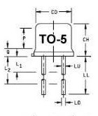
It is important not to damage the glass seals on the leads during assembly. Damage to the glass seals will occur if heat or distortion reaches the area of the glass to metal seals.
To prevent damage the following can be addressed:
First: Design the electrode to insure that current flow does not flow through the glass area of the lower plate. Keep the current flow in the periphery.
Secondly: It is important that the tooling be aligned to bring the full periphery of the part in full contact at the same time to prevent distortion of the lower plate. If the plate distorts the glass seals likely will fail and crack.
Third: If the machine does not have proper follow up – as the projection start to collapse the upper cylinder must maintain full direct force on the part. If there is a delay the full force could come after the nugget is cooling and distortion may occur. Again the plate may distort.
Fourth: The bottom electrode should support the full bottom plate to prevent the possibility of distortion. The current will flow in the periphery while the rest of the plate is supported. This helps to maintain flatness and keeps the glass to metal seal areas cool.
Fifth: Both upper and lower electrodes should have some form of cooling.
Electrode material selection – RWMA Class 2 would be the first choice. If it wears faster than desired then go to RWMA Class 3. I don’t think this application would need RWMA Class 11 which would be the next step up in wear resistance.
For additional information see ARTICLE:
ARE THERE ANY CONCERNS USING DISSIMILAR ELECTRODE MATERIALS TO WELD TO-5 CANS?
Reference: CMW Inc. Catalog
Tuffaloy Products Catalog
RWMA: Resistance Welding Manual, 4th Edition, Section 3
Page 9 of 14
Have a Question?
Do you have a question that is not covered in our knowledgebase? Do you have questions regarding the above article? Click here to ask the professor.