
Projection Welding
Questions and Answers
Resistance welding weld nuts is a projection welding process. In projection welding the part has been formed by design or shape to deliver the force and current at predefined generally small points, shapes or circles. In the case of weld nuts the power is delivered through several small points. Each projection will develop a normal weld nugget. This form of resistance welding uses the part to concentrate the heat and force not the electrode. The traditional weld cycle is squeeze, weld, hold. This is the same as a traditional spot weld. Preheats are not normally used in projection welds.
It is very common operation to weld threaded projection nuts and studs to parts. It is one of the most common fastener systems used in industry. Yes, weld a projection nut to the desired bracket. Spot welding a nut to a steel part could create obstacles due to the large surface area and mass of the nut versus the steel part. Projections on the weld nut eliminate this situation.
Projection nuts are available in many configurations:
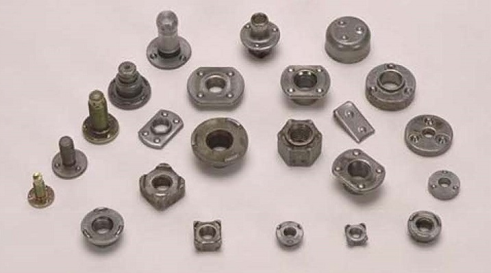
PROJECTION WELD NUTS AND STUDS
Automated feed systems are available for the production of many thousands of parts. Standard machines and processes are available for processing nut and stud components.
References: RWMA – Resistance Welding Manual 4th Edition
AWS – AWS Standard C1.1, Recommended Practices for Resistance Welding
Weld nut set down can be defined as the gap between the weld nut and the stamping. Parallelism of the set down is also a consideration for many applications. At this time there is no accepted industry standard for weld nut or projection weld set down.
The type of part. It’s location in the assembly. The method that force is applied in use. Is it a safety application? Will a coating be applied? These and many other design issues may influence the set down standard being applied to the part. Industry has not developed a common standard.
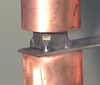
Projection Nut Weld
Below is a sampling of a few simplified descriptions of set down and parallelism applied by different OEM’s.
OEM-1
…shall be set down so that the gap between the base of the fastener and the mating part is no more than 0.3 mm or 30% of the pre-weld projection height (whichever is less) and is not a criterion for welds to be discrepant…
…side-to-side gap shall not differ by more than 0.2 mm, but is not a criterion for welds to be discrepant…
OEM-2
…the fastener maximum gap is 0.1 mm, with a target value is 0.00 mm…
OEM-3
…discrepant if the gap between the welded parts exceeds 20% of the original projection height…
OEM-4
…parallelism of the welding projections of max. 0.1 mm relative to the contacting surface…
As can be seen from the above snippets of information, no one agrees with any one. The values are either percentages of projection heights or hard values, or both. Some consider anything in excess of the stated values to be cause for a weld discrepancy, while others do not. Some address both Set-Down and Parallelism, while others address only one, or the other. Frankly, this level of inconsistency with regard to a single data point is rare in the welding industry.
The possible reasons for these differences are varied. However, they can be boiled down to a few board categories.
• In-Process vs. Structural: Are the projection welds in question strictly manufacturing welds, or are they needed to carry an actual load? An example of a manufacturing application might be a weld nut that has a subsequent bolt and assembly process that might be critical, but once torque is achieved, the welds on the actual nut could instantly disappear and there would be no loss of functionality. Reparability might suffer, but the final product will be fine.
• Type of Loading: The vast majority (but not all) of PW applications have the load applied to the part in a compressive nature. It does not take much imagination to visualize the various OEMs processing their PW applications in differing manners (think applied loads in tension or shear), each with their own level of acceptability requirements.
• Assembly Issues: In some cases, the design can be so tight that excessive (or even moderate) Set-Down values might result in part fit-up issues. This can be seen in areas where many items are coming together in a confined space. As an example, an automotive B-pillar.
• Issues in Paint: While less common, it is possible for the space between the welded parts to act as a trap. The vast majority of weld nuts are located in areas where this not an issue. However, in those cases where any kind of redeposit can occur, you can bet the chorus requesting a ‘Zero’ Set-Down weld will be loud and persuasive.
Taken as a whole, it is best to keep the set down the value to less than 20% of the projection height. As indicated from above one can run into issues even with this ‘Rule-of-Thumb’ due to varying base metal gauges, coatings, and strengths.
References: RWMA – Resistance Welding Manual 4th Edition
AWS – AWS Standard C1.1 Recommended Practices for Resistance Welding
Technical Input by - DONALD F. MAATZ Jr.
In a wire mesh welder many welds are made at virtually the same time. The wire is in contact with the machine, fixtures and electrodes in many places. It is important that the current goes through the weld and not stray through the fixture or machine components. The most important step is machine design. It is imperative that all of the fixtures and support structure of the machine be electrically insulated and nonconductive. This is a machine design issue. The resistance of the wire will retard that flow but the goal is to have a designed path for the flow not a random path.
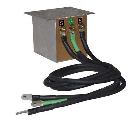
GROUND REACT0R
Secondly all machines should be properly grounded and or have the correct safety devices installed and functional. AWS standard J1.2 Installation and Maintenance describes grounding. Additionally, ANSI Z49.1 offers additional safety information.
If a floating secondary is present a ground reactor will be employed for AC or a ground resistor for MFDC. The ground reactor is attached to both the positive and negative pads and is center tapped to ground. If the secondary voltage exceeds its reactors rating it immediately will flow all current to ground and trip the breaker. The ground resistor works in a similar fashion for the MFDC system except it only connects the negative pad to ground.
Proper electrical grounding is very important and should be performed by personnel familiar with the equipment and safety requirements necessary. Contact a machine builder, reputable distributor or facility engineer.
References: RWMA – Resistance Welding Manual 4th Edition
AWS – AWS J1.2 - Guide to the Installation and Maintenance of Resistance Welding Machines
American Welding Society – ANSI Z49.1 Safety in Welding and Cutting and Allied Processes
Projection welding weld nuts is very common in industry. There is some data available on the subject. One source is AWS. The other is Ohio Nut and Bolt Company. Their site has schedules for many weld nuts and studs to choose from.
Page 5 of 14
Have a Question?
Do you have a question that is not covered in our knowledgebase? Do you have questions regarding the above article? Click here to ask the professor.