
Controls & Transformers
Questions and Answers
A question just came in asking what is duty cycle. This has been answered by a previous article reproduced below:
WHAT IS TRANSFORMER % DUTY CYCLE?
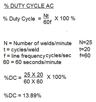
Duty cycle is a measurement of the % of the time that the transformer is conducting current during one minute. This value is used to insure that the electrical components are not operating above their thermal capability. Resistance welding transformers are rated at a 50% duty cycle. Each application may operate at different duty cycle up to and including 100% continuous.
THE FORMULA TO CALCULATE DUTY CYCLE FOR AC is:
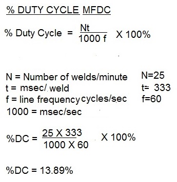
THE FORMULA TO CALCULATE DUTY CYCLE FOR MFDC is:
Other articles in this blog on this subject are:
HOW DO YOU CALCULATE DUTY CYCLE?
WHY IS RESISTANCE WELDING EQUIPMENT DUTY CYCLE RATED AT 50%?
HOW MUCH POWER IS USED RESISTANCE WELDING ON A 150KVA WEKDER?
Reference: RWMA Resistance Welding Manual 4th Edition, Chapter 19
This question has already been answered by another article in this blog:
“HOW DO YOU SIZE A RESISTANCE WELDING TRANSFORMER?”
Please refer to the above article for the answer.
Robot transformers are very robust. They can last for years, if water cooled properly and operated under their rated duty cycle. Overheating a transformer damages the internal insulation and will lead to a short between the primary and secondary coils. Exceeding or running at the rated duty cycle will shorten the life of the diodes in the system.
There are many published resistance welding schedules available for many materials from many sources. In North America the most complete and easily obtained document is an American Welding Society Standard:
AWS C1.1 “Recommended Practices for Resistance Welding”
This document has over forty weld schedules for various materials and processes. They were developed for AC. Twenty-seven of these schedules have a footnote addressing MFDC*.
*FOR DC WELDING EQUIPMENT LOWER CURRENT SETTINGS MAY BE APPROPRIATE
For comparison, there are very few published schedules at this time for MFDC. In fact, development of schedules specifically for MFDC may not happen since all published schedules are used as examples of starting point value “targets”. They are not meant to be dialed in and used as exact values. Industry has learned that the current AC schedules have served well as targets for MFDC equipment.
Sometimes increasing the current and weld time seems to hit a wall as far as nugget growth goes. It is very difficult to grow a nugget larger than the face size of the electrode.
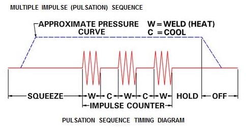
A method that some find successful to increase the face size is to use weld impulses. At the end of the weld cycle schedule an off period of one or two cycles then repeat the weld schedule. The length of the impulses may need to be adjusted to prevent overheated and expulsion.
A larger electrode face size is also an option. This will require a completely new weld schedule. The larger weld face will encourage a larger weld nugget.
Reference: RWMA – Resistance Welding Manual 4th Edition
Page 10 of 40
Have a Question?
Do you have a question that is not covered in our knowledgebase? Do you have questions regarding the above article? Click here to ask the professor.