
There are many published resistance welding schedules available for many materials from many sources. In North America the most complete and easily obtained document is an American Welding Society Standard:
AWS C1.1 “Recommended Practices for Resistance Welding”
This document has over forty weld schedules for various materials and processes. They were developed for AC. Twenty-seven of these schedules have a footnote addressing MFDC*.
*FOR DC WELDING EQUIPMENT LOWER CURRENT SETTINGS MAY BE APPROPRIATE
For comparison, there are very few published schedules at this time for MFDC. In fact, development of schedules specifically for MFDC may not happen since all published schedules are used as examples of starting point value “targets”. They are not meant to be dialed in and used as exact values. Industry has learned that the current AC schedules have served well as targets for MFDC equipment.
As in all example weld schedules, no one should initially start at the actual values listed. Current should always be reduced substantially to allow for differences in equipment, material and set up. The use of MFDC vs AC is one of these differences.
Use the basic values in these AC charts and reduce the amperage to lower values to prevent expulsion. Use a test coupon and make a cold weld to get a feel for the set up. Then proceed from there, adjust the amperage up gradually until the part heats. In a subsequent test a weld will form. In a few trials an acceptable quality weld can be achieved.
Use the AC weld schedules. MFDC will heat faster than AC since there is no cooling that AC experiences as the sine wave crosses zero each half cycle. This is why MFDC may run at lower currents. Test and see what works for you.
The brief quenching/tempering that occurs in AC welding of steel may be beneficial for your product. MFDC does not have this but it can be achieved if desired through pulsing the MFDC control. Remember:
1 AC CYCLE = 16.7 MILLISECONDS
If you believe that the quenching/tempering may help your product pulsing schedules similar to below can be developed with an MFDC control.
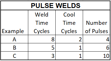
The table is in cycles but since we are setting up an MFDC control use the equivalent time in (milliseconds).
One can note that all three schedules will heat for approximately the same total time of about 30 cycles. The difference is the duration of the heat input and cool time between pulses.
It is generally found that the shorter cool time of one cycle is preferred. Additionally, the shorter heat inputs with more pulses may prove to be better.
Remember always begin the test with coupons at current values well below where you expect to end up.
Reference: AWS C1.1 - Recommended Practices for Resistance Welding
RWMA - Resistance Welding Manual 4th Edition