
Spot Welding
Questions and Answers
Weld nugget size and shape are dependent upon the welding parameters and the condition of the parts being spot welded. Electrode size, shape and location on the part can have an effect. The weld schedule which is the power input and force of the electrodes will affect nugget formation. The part material, surface conditions and flatness will contribute to the nugget formation.
Most weld schedules call out a desired nugget size. The welds can be cross sectioned and measured. The most common method is to pull the two welded surfaces apart to expose the nugget. This is performed with a vice, using pliers, hammer and chisel.
The result in graphic form is shown below:
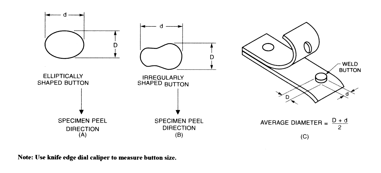
The nuggets may not be perfect circles. To calculate the nugget size all are calculated using the same simple average of the dimensions as shown. Weld nugget size is the normal specified dimension. Weld nugget area is generally not specified. If desired the area is desired, it can be calculated
Using the area of a circle: A = πR2 or A = πD2/4
In the case of the “C” exhibit above this formula will work. For exhibit “A” or “B” the math becomes complicated. Every nugget can vary in shape and size as suggested by exhibit “A” and “B”, depending upon the weld conditions. Calculation of the weld area for these examples is a mathematics exercise. The possible variations too many for consideration in this blog.
References: RWMA Resistance Welding Manual 4th Edition
AWS Standard – C1.1 Recommended Practices for Resistance Welding
It is a common practice to dress resistance welding caps used in robotic and job shop applications. Many dress at breaks or shift changes. In automated operations some dress a very small amount between each part as the line moves. The goal is to maintain a relatively consistent electrode face welding the part. At some point a limit to the material removal is reached and the cap must be changed. The question is:
How much material can be removed before the cap will fail to function?
The assumption is that the dressing removes all surfaces problems and the part is functional. The only consideration is face to waterhole material thickness. Obviously dressing into the water hole is too far. In a nonscientific test observed personally, it was pointed out that the facing thickness is the controlling factor.
When the face thickness is not strong enough to withstand the weld force being applied the electrode face will collapse. Electrode or cap dressing must end before this. Obviously this face thickness can be affected by the face design of the cap or electrode.
Many end users specify a dressing ring on the cap. Some companies have standard parts with the dressing rings as standards. Some of the rings are limits. Other rings mark the water hole. The actual testing and verification of their functionality is beyond the scope of this blog.
Reference: RWMA – Resistance Welding Manual 4th Edition
This combination of very thin brass a very conductive material to a strong, resistive stainless material is very difficult. The brass due to its conductivity will be slow to heat up. The stainless will heat up and probably conduct heat into the brass. Since the brass is so thin it will suddenly overheat and melt through.
If any, there is a very small window for success.
Most modern controls have current feedback and monitoring capability built in. They read and report each half cycle or millisecond depending upon the system being used. Older equipment may not have these features. The use of a monitor offers data confirmation, storage capacity, off-loading capability and security.
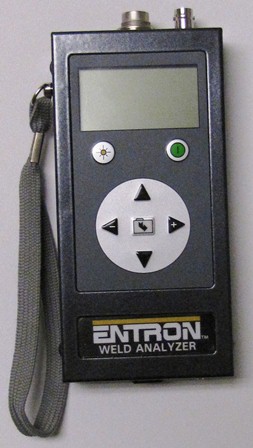
HAND HELD CURRENT METER
DeskTop Current Monitors with more features are readily available.
The resistance made when the electrode touches the workpiece is created by:
• Composition of the workpiece
• Surface condition of the workpiece – rough, smooth, clean, dirty
• Conductivity or resistivity of workpiece surface
• Composition of the electrode
• Surface condition of the electrode – rough, smooth, clean, dirty
• Conductivity or resistivity of the electrode surface
• Pressure or force of the electrode on the workpiece
Sandblasting has a dramatic affect upon the surface condition of the workpiece. Depending upon the media used for sand blasting the surface resistance can be a problem?
Page 9 of 44
Have a Question?
Do you have a question that is not covered in our knowledgebase? Do you have questions regarding the above article? Click here to ask the professor.