
Projection Welding
Questions and Answers
It is a law of physics that current flowing through a conductor will generate a flux field around it. This flux field is a magnetic field and is the basis of electric motors, generators, and transformers.
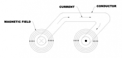
MAGNETIC FIELD AROUND ELECTRICAL CONDUCTOR
All resistance welding machines have this flux field in the throat or loop area.
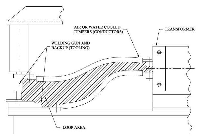
THROAT OR LOOP AREA WITH MAGNTIC FIELD
Any magnetic material that enters this throat area will be affected by the magnetic field, if this is an AC machine. DC or MFDC machines still have magnetic affects but do not have the reactance of an AC machine and will not cause the part to heat up and drain the power from the weld.
Another issue is that as the welding machine initiates it could cause parts indexing into the throat of the machine to move if they are not held in the fixture properly. Tooling must hold parts tightly to prevent them from moving as the magnetic field builds and collapses while the parts are moving into the throat. The magnetic field is a given. It will not go away.
Over time weld flash builds up on the frame and tooling. If it is not removed it can build up heat and drain the power of the welder. Stray current paths can occur in the weld flash build up and unusual operations can be noted. This can be solved by preventive maintenance and weld flash removal.
References: RWMA Resistance Welding Manual 4th Edition
AWS J1.2 Guide to Installation and Maintenance of Resistance Welding Machines
Many parameters if not controlled could be a factor and lead to cracks in or near a projection weld.
MATERIAL: The material being welded is one factor. It could be a brittle material after nugget formation without a tempering or post heat treatment operation. The material might be one which tends to form voids if not forged during the weld to heal those voids. This could be a brittle material that must be annealed with post heat treatment after nugget formation. The cracks could form in the weld or around the periphery without treatment.
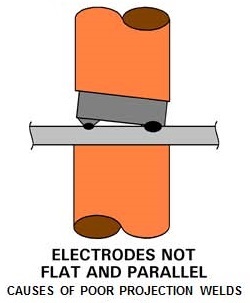
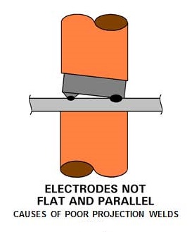
TOOLING or PART ALIGNMENT: If the projections do not contact the part all at once, those in contact will carry too much power and others none. Those with too much power may expel metal. As set down occurs the others will make contact. Then likely will arc upon contact. Expulsion occurs again. Any or all of these welds could show discrepancies.
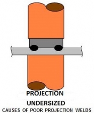
PROJECTION SIZE AND SHAPE: If projections are not equal in size some which are short in height will make contact after other and have the power problem described in alignment. If they are equal height but different size/diameter they will collapse at different speeds. This will steal the power from those that have not set down and last projections to make contact may be weak and fail.
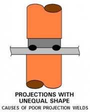
UNEQUAL SIZE UNEQUAL SHAPE
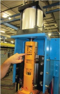
FOLLOW-UP: If all is otherwise good the machine must be able to deliver continuous full force as the projections collapse. Large massive press welders may have an inertia in their massive cylinder heads. This is a delay factor. Due to this inertia the cylinder may hesitate just when the cylinder needs to drive the hot projection down and forge it. This leads to nuggets with cracks or weak joints. This same situation could be caused by a faulty servo or cylinder. Machine maintenance, low-inertia-machines or fast-follow-up holders are the correction for this condition.
 V
V 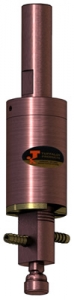
LOW INERTIA MACHINE FAST-FOLLOW-UP HOLDER
WELD SCHEDULE: The proper weld schedule for the material being welded is always necessary. Weld schedules with the appropriate pre and post treatments must be chosen when required to insure the formation and forging of a strong nugget. A source of projection weld schedules is AWS C1.1.
Another article in this blog on this subject is:
What are the Do's and Don'ts for projection welding?
Reference: AWS C1.1- Recommended Practices for Resistance Welding
RWMA - Resistance Welding Manual 4th Edition
There is not a lot of data published on projection welding. There is a table published by AWS in their specification AWS C1.1 Recommended Practices for Resistance Welding. Table 48 lists process requirements for cross wire welding hot and cold drawn steel wire. It should do well as a starting point for this application.
In a series weld generally an upper gun puts power in through one weld point which travels through that joint into a common lower platen. The power flows through this platen to the location of the second weld and then through this weld to the second weld gun and back to the transformer. Two welds are made with one operation. Care must be taken to keep the welds separated to avoid shunting currents. Shunting currents are currents that do not flow through the desired weld joints.
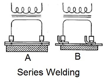
In the given wire welding situation 4mm wire replaces the upper piece. Spacing must be adequate to avoid current flow through the wire. Then using the chart in C1.1 try the lowest set down listed at 15% for your wire size. Take those values and reduce the power by 30 to 50% and see what happens for the first trial welds. Then adjust up or down on the settings until something happens. If nothing happens at 15% set down settings go to 30% settings and try the same process again.
Always approach from safe low power setting to make sure that part, people and equipment are safe in this trial and error scenario.
The values listed in C1.1 will make a weld for the material listed. Your material and equipment may vary but a weld can be made at similar settings.
Reference: AWS C1.1 Recommended Practices for Resistance Welding
RWMA Resistance Welding Manual 4th Edition
Yes, projection welds like any spot weld if not performed properly have the potential to generate weld spatter or expulsion. The variables that must be controlled are alignment, projection size, shape or missing, force follow-up and weld schedule. Their variation may result in spatter if:
ALIGNMENT: If the pressure is not applied and the multiple projections do not make contact at the same time or with the same pressure, one or more will carry most of the current and overheat. This overheated projection or projections have the potential to expel material. The final projection when it makes contact will do so under current which means an arc will occur. An arc can always lead to expulsion.
PROJECTION SIZE OR SHAPE: When welding multiple projections, if the projections are not the same size, shape or missing there is a potential for inconsistent welding. When the projections make contact at the same time, but they are different sizes they can heat at different rates. One projection can overheat which could lead to expulsion. If size is dramatically different, one projection may not make initial contact. When the other projections begin to collapse due to carrying too much current the then the last projection will make contact with the current on and make an arc. Flash, expulsion or spatter could result from the arc or from the over heated original contacted projections.
FORCE FOLLOW-UP: It is imperative that as the projection begins to heat up and collapse that the weld head maintains force and full pressure on the projection as it collapses. This insures a good strong weld. If the weld head sticks or is slow the weld strength will suffer and the strength will be low or in an extreme case no weld and flash, expulsion or spatter could result.
WELD SCHEDULE: A proper weld schedule is always important to efficiently apply the proper force, bring the projections up to temperature and forge the weld with the proper fast follow up.
Projection welding parameters are readily available in published weld schedules referenced below. In general they have relatively short weld times and perform very well as documented. There are cases in which the circumstances in manufacturing are not ideal and variations from the standard are necessary. In these circumstances a change in the weld schedule may help.
As stated in another article “How Do I Dress a Resistance Welding Electrode”, the best way is to remove the electrode and remachine it in the tool room where it can be done accurately. For projection welding this may be the only option if the electrode has elaborate machined surfaces or dimensions. If the projection face is merely a flat face which many are other option are possible.
There are no specific tools that I would recommend for dressing.
Manually a block of wood with emery paper on one or both sides as needed. Close the electrodes with lite pressure and rotate the emery paper till the desired flatness is achieved. This could also be a two sided fine flat file followed by fine emery paper.
Page 10 of 14
Have a Question?
Do you have a question that is not covered in our knowledgebase? Do you have questions regarding the above article? Click here to ask the professor.