
Projection Welding
Questions and Answers
The answer to this question is maybe. It will depend upon several variables that were not supplied with this inquiry.
MATERIAL BEING WELDED – stainless steel, low carbon steel and aluminum have increasing current requirements.
MATERIAL THICKNESS – This will dictate the size of the projection. Projection size will dictate current amperage, time and force requirements.
PRODUCTION RATE – Number of welds per minute.
TYPE OF MACHINE/TRANSFORMER – Press welder, AC, DC, MFDC
With this information one can size the transformer needs and make an informed decision.
In projection, resistance brazing or spot welding, residue from the process eventually builds up on the face of the electrode.
CLEANING COPPER SPOT WELDING ELECTRODES:
In the case of spot welding mushrooming is also present. Spot welding electrodes are normally copper alloys making a machining process on or off the machine the most practical method of mushroom and residue removal.
CLEANING COPPER, COPPER TUNGSTEN (RWMA Class 11), MOLYBDENUM (RWMA CLASS 14) AND PURE TUNGSTEN (RWMA CLASS 13) PROJECTION & RESISTANCE BRAZING ELECTODES:
In projection welding and resistance brazing there can be some mechanical wear of the electrode face but frequently there is a buildup of fluze or foreign product generated from the weld, weld flash or???. At some point this buildup may interfere with part loading or locating. Cleaning becomes necessary. Depending upon the electrode material a simple machining process may be called for if it is a copper alloy.
In this scenario there are two possibilities:
1. The weld nut has come off.
2. The weld nut is still adhering the part.
In either case the weld nut projection geometry has been altered. The Question is what should be done to correct for this?
In Case # 1 the nut should be scrapped and new weld nuts welded to the part. This may require some refinishing of the weld blank at the weld location prior to rewelding. A clean smooth surface is desired prior to rewelding. Additionally, a process adjustment may be required to make an acceptable weld.
In Case # 2 this is a reprocess or repair. The only acceptable repair the Detroit-3 have ever considered is a form of arc weld to the exterior of the nut. This could be a MIG-braze if the metal is thin. If thicker a GMAW may be employed. A reweld would never be acceptable. There are too many variables to overcome to achieve an acceptable weld.
It is likely that a standard published 3 or 4 projection weld schedule does not exist in the literature. The options are start testing from scratch or look at spot welding data for the same material that may exist.
The best way is to use a known similar weld schedule to estimate for the initial test coupons.
Simply use the data for one spot weld and multiply current and force by three or four depending upon spot spacing. Time stays the same.
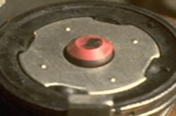
FOUR PROJECTION PART
Projection nut welding is done every day in sheet metal fabrication shops. In most, tooling is used to locate the nut on the part. A centering pin is frequently part of this tooling.
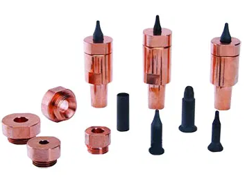
AUTOMATED NUT FEED TOOLING COMPONENTS
These pins function as a locator and in most cases also have to be an electrical insulator to prevent current flow through the pin and damage to the threads of the nut. To prevent this the locator pin is electrically insulated by some means.
The question posed above is: What material is best for nut welding? This applications demands good wear, long life and insulation. Options in the marketplace are:
Solid Ceramic pins
Metallic Pins (insulated by an insulating sleeve or coating in the holder)
Ceramic coated metallic pins
All three are being used. They all work. They all have pros and cons.
In automated systems the pin will see impact abuse as the parts are loaded. Each time the nut loads friction can cause wear on the ceramic surface or coating. Flash can cause the pins to stick and not retrack, increasing the abuse. The pins take a lot of abuse and see a lot of heat. We have: IMPACT, FRICTION, FLASH and HEAT. These problems lead to nut misfeeds or thread arcing and damage.
Which of these issues is present?
Which pin design is the best to solve that issue?
Is it cost effective?
Is it available in the quantity needed?
A material with a yes to all of these questions is the best material for the application.
A local distributor or supplier will be able to help in the evaluation of the best option for the application.
Reference: RWMA – Resistance Welding Manual 4th Edition
Page 6 of 14
Have a Question?
Do you have a question that is not covered in our knowledgebase? Do you have questions regarding the above article? Click here to ask the professor.