
Projection Welding
Questions and Answers
Capacitor Discharge
A capacitor discharge welder is known to discharge its full output very quickly into the weld joint. The weld may be a ½ cycle or so. My knowledge of CD equipment is minimal. I can’t offer any comments on life or maintenance. I understand they can be more expensive to purchase as compared to AC.
AC
In comparison a standard AC welder makes a projection weld in several cycles 5 to 20 or more cycles. This is a much slower weld and may impart a different heat affect than the CD welder which is short and fast.
AC equipment is robust can operate for a very long time with little maintenance. Force, follow-up and alignment are the most important issues to keep an eye on.
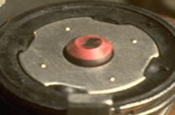
PROJECTION WELD PART
MFDC
Recently the MFDC segment of the market has been developing transformers with a “Fast Rise” to duplicate the Capacitor discharge. Their goal is to produce vary large weld currents in 10, 20 or 30 milliseconds. MFDC generates a DC output so the current can flow longer than an AC ½ cycle. They have been successful. This a promising new development.
Reference: RWMA Resistance Welding Manual 4th Edition
Nut welding is a very common operation in manufacturing. Hundreds of thousands of nuts are welded every day. Most are loaded and welded on automated lines. The tooling and fixtures include locating equipment to ensure the nut is positioned properly each time. In many cases a “Pin” is used to locate the hole in the nut and hold it in place. This pin frequently must be insulated to prevent current flow into the threads of the nut. If there is flow it will probably be an arc which will damage the threads.
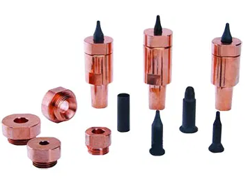
AUTO NUT FEED COMPONENTS
Projection welding is a very widely used process from cross wire welding of fencing, to nut welding, to water tight water heater fittings, to a handle on a kitchen measuring cup. They all perform different important functions but all depend upon the shape of the part to concentrat the heat and power for nugget formation. The machine and electrodes have to hold the part in place for this to occur or we have chaos.
Factors that are important are the machine functions of pressure current and time. AWS covers general maintenance of the machine and will not be addressed here, see the reference.
This is an interesting question. Most people are concerned about the height of the projections varying or not being present. The flatness of the base metal is considered a given. Any variation in the projection or the base metal that creates the same gap can lead to a welding issue. The question is how much gap can be tolerated.
After the force is applied before the current is initiated full projection set down is needed to eliminate all gaps in order to prevent material expulsion and maximize weld strength. Gaps in a ring projection or multiple projection all have the same requirement for flatness. Flatness helps to make complete set down and full contact to ensure the current is evenly conducted through all of the projection areas at the same rate. This will maximize nugget formation as desired either as a ring, single or multiple projections.
A search of the literature found one source that listed allowable tolerances for projection heights.
AWS C1.1 – “Recommended Practices for Resistance Welding”
Table 46 listed a height tolerance up to: +/-1.27 mm (+/-0.005 in) for material over 1.27 mm (0.050 in) thick.
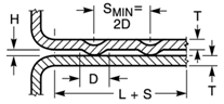
PROJECTION HEIGHT "H"
For thinner material and complete information consult AWS C1.1 – “Recommended Practices for Resistance Welding."
Reference: AWS C1.1 Recommended Practices for Resistance Welding
RWMA - Resistance Welding Manual 4th Edition
Resistance welding weld nuts is a projection welding process. In projection welding the part has been formed by design or shape to deliver the force and current at predefined generally small points, shapes or circles. In the case of weld nuts the power is delivered through several small points. Each projection will develop a normal weld nugget. This form of resistance welding uses the part to concentrate the heat and force not the electrode.
Due to this unique design feature the size of the electrode is not a factor. The electrode is normally flat and at least the size of the part mating surface. It should be larger than the projection weld pattern area to prevent heat buildup and provide support to the part. The size of the electrode has little influence on the weld since the projection concentrates the current and force not the electrode. Factors besides the part size that might influence the electrode selection could be: the available equipment, available tooling, expected power requirement and anticipated force. The electrode should be larger than the part being welded as shown.
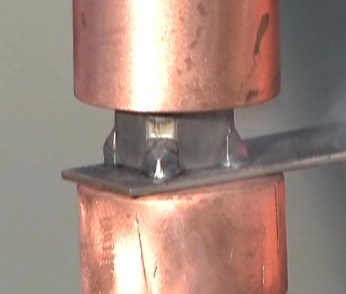
PROJECTION WELD NUT
In ring projections the electrode diameter should be at least twice the diameter of the projection ring. So the answer is yes it could be a 6 and 8 MM electrode mix is they fit the parts properly. Or two 8MM’ s if you want common electrodes to reduce electrode inventory?
In some welds individual electrodes are used on the one side and a common bar electrode is used on the other side. Fencing can be projection welded in this manner.
Reference: AWS Standard C1.1 Recommended Practices for Resistance Welding
RWMA – RWMA Resistance Welding Manual 4h Edition
Page 4 of 14
Have a Question?
Do you have a question that is not covered in our knowledgebase? Do you have questions regarding the above article? Click here to ask the professor.