
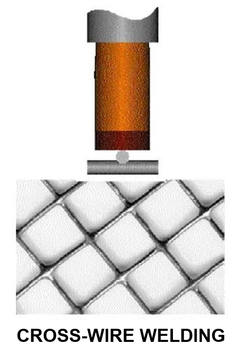
Projection Welding
Questions and Answers
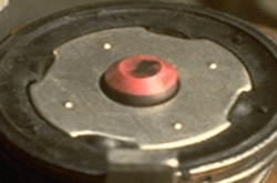
Projection weld nuts are used in many industrial applications. Many are piloted weld nuts as shown below.
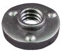
THREE PROJECTION WELD NUT WITH PILOT RING
To make a good projection weld several issues must be considered:
They are:
1. The purpose for the pilot on a weld nut: The short answer is to help protect the internal portion of the weld nut from expulsion and other foreign material while being welded. The tooling and part associated with the projection welding (PW) of forged or coined weld nuts (think solid projections) must be properly designed, to include ways to minimize expulsion getting into the threads. A proper pilot on the nut can help in this regard.
2. The tooling used is also really important: The pin package and other portions of the tooling must be robust, able to hold the part in a repeatable location, and place the weld nut accurately and centered on the hole. Items that need to be considered as part of this design are the gauge of the material being welded, the thickness of the nut, the height of the projections, and where electrical insulation is needed.
3. The proper size of the hole in the part: The stated clearance value of 0.002” is too small for the size of the application. One PW design standard I am familiar with specifies for an M10 piloted weld nut (close to the 3/8 nut in this question) a 15.0-15.15 mm hole Ø for a pilot on the nut, with a pilot of between 12.4 – 12.7 mm Ø. The aforementioned standards would result in clearances of roughly double reported above.
4. The welding equipment must be capable, and the schedule proper for the application: This one is very application dependent. There is an article in the Welding Journal (Sep-2010 - RWMA Q & A) that might be helpful to address machine and weld schedule.
References: RWMA – Resistance Welding Manual 4th Edition
AWS – AWS Standard C1.1 Recommended Practices for Resistance Welding
Technical Input by - DONALD F. MAATZ Jr.
Milco Manufacturing Company
There are articles on constant voltage and constant current in this blog:
SHOULD CONSTANT CURRENT EVER BE USED FOR PROJECTION WELDING?
These explain the advantages of using constant voltage and constant current.
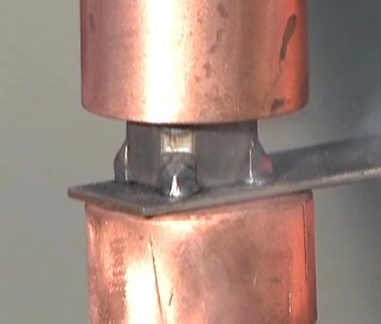
PROJECTION NUT WELD
This blog deals with the resistance welding process. It does not offer any input on manuals set up or maintenance of individual machines. Consult your local machine dealer or manufacturer for assistance.
Reference: RWMA Resistance Welding Manual 4th Edition
We will talk about the weld schedule first. There is no formula for a weld schedule. If you know a schedule for a similar single projection weld it can be applied to your application. If you are welding several projections of the same size and they are spaced modestly multiply the current and force by the number of projections. Current and time stays the same.
Ref: Blog article:
HOW DO YOU DEVELOP A PROJECTION WELDING SCHEDULE?
If a weld schedule is not available then references are available and are listed in the above article. Additionally the references listed below have weld schedules for projection and spot welding various thicknesses of materials.
A spot weld schedule can be used as a starting point. The multiplier noted in the above article will apply applies here.
Remember always start your set up with the power on the cold side to avoid any major expulsion. Then adjust the power up slowly.
When you have achieved a weld nugget it is measured just as in spot welding:
WHAT IS THE FORMULA FOR CALCULATING A WELD NUGGET?
Measure the nugget in two directions at 90 deg apart. Average the two values and you have the answer.
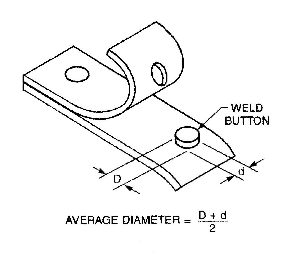
WELD NUGGET CALCULATION
Reference: AWS C1.1 Recommended Practices for Resistance Welding
RWMA Resistance Welding Manual 4th Edition
Tuffaloy Product Inc. Catalog
CMW Inc. Resistance Welding Products Catalog
After projection welding the nut surface might be damaged and coated with weld residue of unknown chemistry. This coating can act as a sponge and hold humidity and actually contain iron, copper and brass and many other chemical components. Some of these can be targets for rust. Bare metal may have been created during the welding process which is also a target for rust formation in the presence of humidity.
A brief search on the web found that steel can begin to rust within a few hours if in a humid environment. The amount of humidity and bareness of the steel determines the speed that this occurs. Some nuts are coated to retard corrosion. Welding may partially affect this coating. Iron will rust even faster than steel.
To prevent rust reduce the moisture and humidity. Rust preventive coated nuts may reduce rust occurrence.
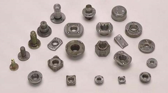
ASSORTED WELD NUT
References: RWMA - RWMA Resistance Welding Manual 4th Edition
This is an interesting question. It brings up part placement, accuracy, consistency and safety. The part needs to be loaded accurately each time and at the same time the operator must be safe. Safety will be briefly discussed here. There are a few general items that can be considered:
• Normally operators have eye protection and gloves for protection from flash or burrs on the metal components that may be handled
• Tooling or fixtures are common which accept the part components and hold them in the proper position and orientation prior to welding
• Auto loading mechanisms are frequently used to load parts (nut welding)
• Auto loaded or manual loaded, the parts must be positioned to ensure that the electrode force is perpendicular to the projections. The goal is even perpendicular force distribution. If the electrode is at an angle skidding may occur and weld strength may be compromised along with part distortion.
• Robotic systems frequently are used for part placement
• In manual loading, safety systems are employed to ensure that the operator is clear before the welder can be initiated.
• Robotic or Automatic systems are frequently enclosed in caged areas for safety
From a resistance welding point of view the part must be held or positioned in the proper orientation and alignment to meet the part specification. It must stay that way until the electrodes have closed on the part. Fixtures or tooling frequently perform this function.
PIN LOCATING 4 PROJECTIONS
In some applications part desing fullfils this need
Parts are generally fixtured and loaded manually or with auto loading systems. This will allow for hands to be out of the weld area before weld activation. In manufacturing, safety systems are frequently employed to ensure hands have been removed before the weld cycle will activate.
Local machine manufacturers and suppliers will be familiar with the local regulations and available safety equipment for fixturing and personal protection.
Safety requirements vary. KNOW, UNDERSTAND and ADHERE to the prevailing Safety Standards in your location for manually loaded parts or auto loading systems.
Safety implementation is beyond the scope of this blog.
Reference: RWMA - Resistance Welding Manual 4th Edition
Page 1 of 14
Have a Question?
Do you have a question that is not covered in our knowledgebase? Do you have questions regarding the above article? Click here to ask the professor.