
Controls & Transformers
Questions and Answers
This answer has been given in the reverse mode in another published article:
HOW MANY PRIMARY AMPS WILL A 64 KVA RESISTANCE WELDING TRANSFORMER PULL?
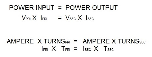
If you look at this referenced article, several important data points are necessary in order to calculate the output of the 10 KVA transformer. The turns ratio being the first. The turns ratio shows that power in the primary equals power in the secondary. Secondary voltage is a second necessary data point.
The actual current will be influenced by the secondary circuit.
If you know your turns ration and primary amps at least an estimate can be made. Do study the above document so that duty cycle and all factors are considered.
References: RWMA - Resistance Welding Manual 4th Edition
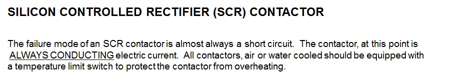
The SCR contactor is a component of the AC resistance welding control. The control initiates the time and frequency of the SCR’s activation and passing of current. This current of course goes to the transformer primary and is converted to low voltage high current in the secondary of the transformer to travel to the electrodes and make the spot weld. The SCR is the on off switch for this process. It functions on every half cycle of current as instructed by the control.
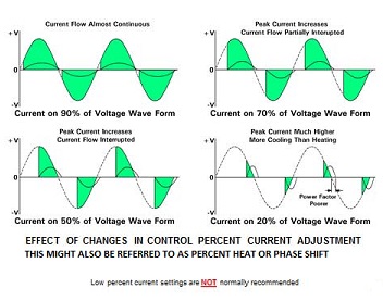
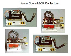
The SCR contactor is a solid state device with no moving parts. It is very fast and reliable. As with all electronics it is sensitive to heat and must be cooled by air or water depending upon its service rating. A temperature limit switch is recommended.
If one of the two SCR’s has failed as noted above, it usually fails in the on mode, The transformer will be under full power. The control will not see this. If activated the electrodes will get VERY HOT. The circuit breaker may trip?
Test voltage across the electrodes when open if they have voltage the SCR has failed.
Sometimes SCR’s don’t short out and trip the breaker. Occasionally they fire erratically. If only one SCR fires, this is called half cycling. The transformer is out of balance and will make a grunting sound, vibrate, current will spike and the breaker may trip.
Generally, a failed SCR leads to voltage when there should not be any at the electrode. The second less frequent events are strange erratic happenings, sounds and tripped breakers. If you are not sure what you are dealing with make a call to your local equipment supplier or distributor who likely has dealt with this situation before.
Reference: RWMA Resistance Welding Manual 4th Edition
The SCR contactor is a component of the resistance welding control. The control initiates the time and frequency of the SCR’s activation and passing of current. This current of course goes to the transformer primary and is converted to low voltage high current in the secondary of the transformer to travel to the electrodes and make the spot weld. The SCR is the on off switch for this process. It functions on every half cycle of current as instructed by the control.
The SCR contactor is a solid state device with no moving parts. It is very fast and reliable. As with all electronics it is sensitive to heat and must be cooled by air or water depending upon its service rating. A temperature limit switch is recommended.
If one of the two SCR’s has failed the transformer will be under full power. The control will not see this. If activated the electrodes will get VERY HOT. The circuit breaker may trip?
Test voltage across the electrodes when open if they have voltage the SCR has failed.
Sometimes SCR’s don’t short out. Occasionally they fire erratically. If only one SCR fires, this is called half cycling. The transformer is out of balance and will make a grunting sound, vibrate, current will spike and the breaker may trip.
Generally, a failed SCR leads to voltage when there should not be any at the electrode. The second less frequent events are strange erratic happenings, sounds and tripped breakers.
If you are not sure what you are dealing with make a call to your local equipment supplier or distributor who likely has dealt with this situation before.
Reference: RWMA Resistance Welding Manual 4th Edition
The transformer tap switch of a resistance welding transformer is installed on the windings of the primary side of the transformer. By changing the tap switch one is changing the turns ratio of the transformer. When the turns ratio changes it will change the voltage in the secondary coil. Tap 1 will produce the lowest secondary voltage and the highest tap will produce the highest secondary voltage and potentially the maximum KVA rating of the transformer.
See article:
DO I NEED TO INSTALL A SERIES BAR TO MEASURE THE TURNS RATIO OF A RESISTANCE WELDING TRANSFORMER?
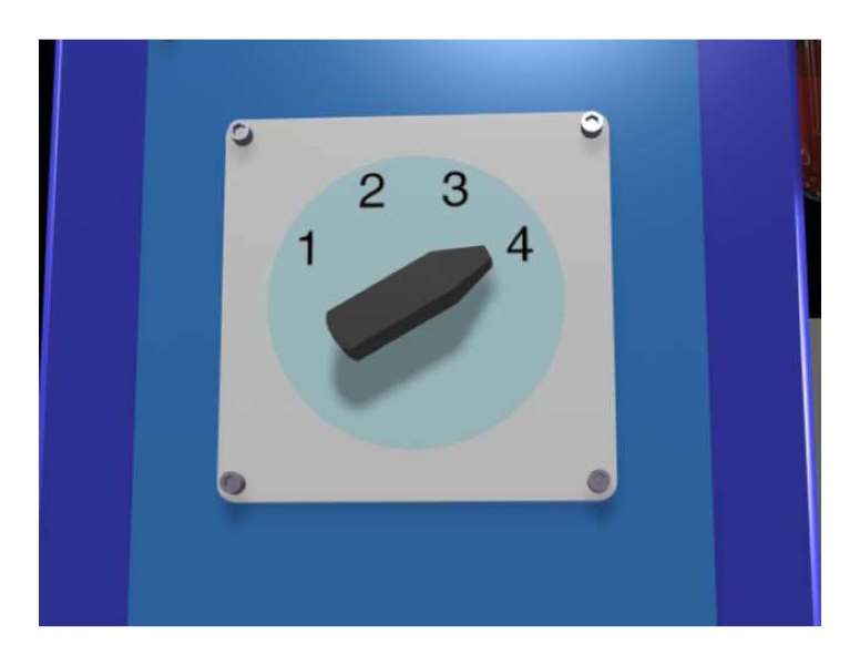
PRESS WELDER TAP SWITCH
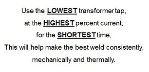
As a suggestion to get the best performance:
To see other articles on this subject do a search on transformer taps in this blog.
References: RWMA – Resistance Welding Manual 4th Edition
This answer to this question is included in the answer of another article:
HOW DO YOU SIZE THE PRIMARY CONDUCTORS FOR AN AC RESISTANCE WELDING TRANSFORMER?
It builds upon the formula:
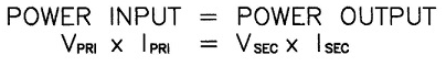
In this instance we have a 250 KVA AC machine transformer with a high tap of 25.8 volts and a low tap of 12.9 volts.
All of this depends upon not overheating the transformer Therefore we must operate at no more than 50% duty cycle. The above article explains how to insure the transformer is operated under safe conditions:
If the Duty Cycle or Weld Current are not known or this is a general purpose machine:
1. Divide the transformer nameplate KVA by the primary voltage.
2. Multiply that result by the square root of 0.5 (RWMA transformers normally are rated at 50% Duty Cycle)
3. The result is the Primary Effective Continuous Thermal Current (ECTC).
4. Refer to the Ampacity Chart of the cable type to be used. Select the size based on the Primary Effective Continuous Thermal Current (ECTC).
Ampacity charts are based on the National Electric Code (NEC). There may be other state, local or company standards that must be followed.
Reference: National Electric Code
RWMA Manual Chapter -21.7
Roman Manufacturing Inc.
Page 6 of 40
Have a Question?
Do you have a question that is not covered in our knowledgebase? Do you have questions regarding the above article? Click here to ask the professor.