
An inquiry came in suggesting that two forces are responsible for creating a resistance weld. Let’s examine this question. To do so we will look at two previously published articles in this blog:
“WHAT IS AC RESISTANCE WELDING”
AND
“WHAT IS THE DEFINITION OF RESISTANCE WELDING”
Per the definition of the Resistance Welding Manufacturers Alliance:
RESISTANCE WELDING IS THE JOINING OF METALS BY APPLYING
PRESSURE
AND PASSING
CURRENT
FOR A LENGTH OF
TIME
THROUGH THE METAL AREA WHICH IS TO BE JOINED
To expand upon this PRESSURE is provided by mechanical means of pneumatic or hydraulic cylinders, servos, cams and sometimes manually. Normally it is measured in pounds, kilos or equivalent. It is applied in sufficient amount to contain and control the weld to a specific desired area, before the current is applied. CURRENT is supplied by the control and transformer. The transformer does just that transforms relatively small current input from the buss to many thousand amperes needed for resistance welding at people safe low voltages. The control determines the amount of CURRENT and the TIME.
Heat is generated according to JOULES LAW
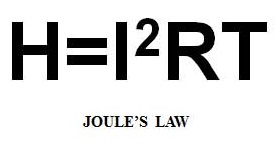
The heat is generated by the current squared, times the resistance, multiplied by the time. It is the current flowing through the area to be joined for a length of time and the resistance at that joint which generates heat to make a joint. The force holds all of this together and forges the joint as it forms and cools it down.
In answer to the question posed the resistance weld is formed per Joules law and the application of pressure and current for a length of time. This is commonly referred to as “PCT”. Three forces or factors control the resistance welding process. The welding machine provides this through this through the:
Pressure System – (P)Pneumatic or hydraulic cylinders or servos
Power System - (C) of the transformer and conductors
Controls – (C & T) Meters the time and amount of current and machine operations
AC resistance welding uses AC current and transformers for the power in resistance welding. Most rocker arm and press welders have been manufactured with AC power supplies.
The equipment can also be DC direct current.
In the last thirty years MFDC mid frequency direct current has become the go to equipment for automated robotic systems and many other applications.
There are many articles published in this forum about the advantages and disadvantages of the AC, DC and MFDC systems. One can find these by performing a search on the home page of this forum.
Reference: RWMA – Resistance Welding Manual 4th Edition