
Spot Welding
Questions and Answers
Aluminum has a very high expansion and contraction during heat cycles. This in combination with a narrow plastic range make the weld nugget subject to crack formation during solidification. The fast contraction can lead to weld failure as welded.
Normally resistance welds are made with fast heat up. With two water cooled electrodes on the surface of the aluminum it will cool down fast. This is where the problem begins. There is a shrinkage in volume as it shrinks so the electrode system must have good fast follow up in order to maintain constant force.
Another tool sometimes used is a slowed cool down along with carefully timed forging to reduce the shrinkage voids.
If the voids are reduced or eliminated the aluminum weld will have greatly improved integrity.
American Welding Society - AWS Standard Publication C1.1 Goes into depth on the methods and has weld schedules for a few sample aluminum materials to explain the processes used.
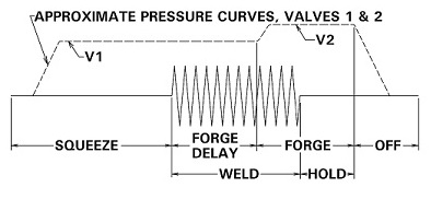
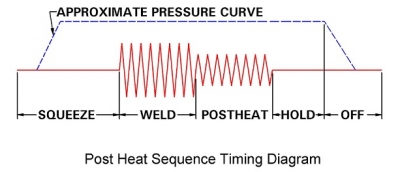
As stated in the AWS C1.1 the timing of the post heat and forging action is critical in order to close the voids before the aluminum has solidified but not too soon or one could dissipate the heating effect of the forging current.
See:
CAN ALUMINUM WELDS BE IMPROVED WITH FORGING?
Reference: RWMA Resistance Welding Manual 4th Edition
AWS Std C1.1 Recommended Practices for Resistance Welding
Copper because of its high conductivity is very difficult to resistance weld. Joule’s Law states:
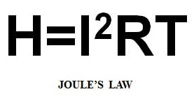
Copper has relatively no resistance. It does not want to heat up. So very high current would be needed. The reference materials state it is impractical to weld.
Resistance brazing methods are used., the heat is generated by using high heat generating refractory metal electrodes of RWMA Class 13 or 14. They get hot and transfer heat into the copper. Zinc and tin coated copper are used as a semi braze alloy to melt and form a joint but may be limited by their low joint strength.
The most reliable option may be a true resistance braze. An intermediate true braze material is place in the braze joint and “Joule’s heating occurs there and forms a braze when it resolidifies.
These topics are discussed in more detail in the following articles:
CAN COPPER BE RESISTANCE WELDED?
HOW CAN THE WELD STRENGTH BE IMPROVED FOR RESISTANCE WELDING ZINC OR TIN COATED COPPER?
A resistance braze is probably the preferred process to bond the two pieces of 1.5 mm (0.059”) copper together.
Reference: RWMA – Resistance Welding Manual 4th Edition
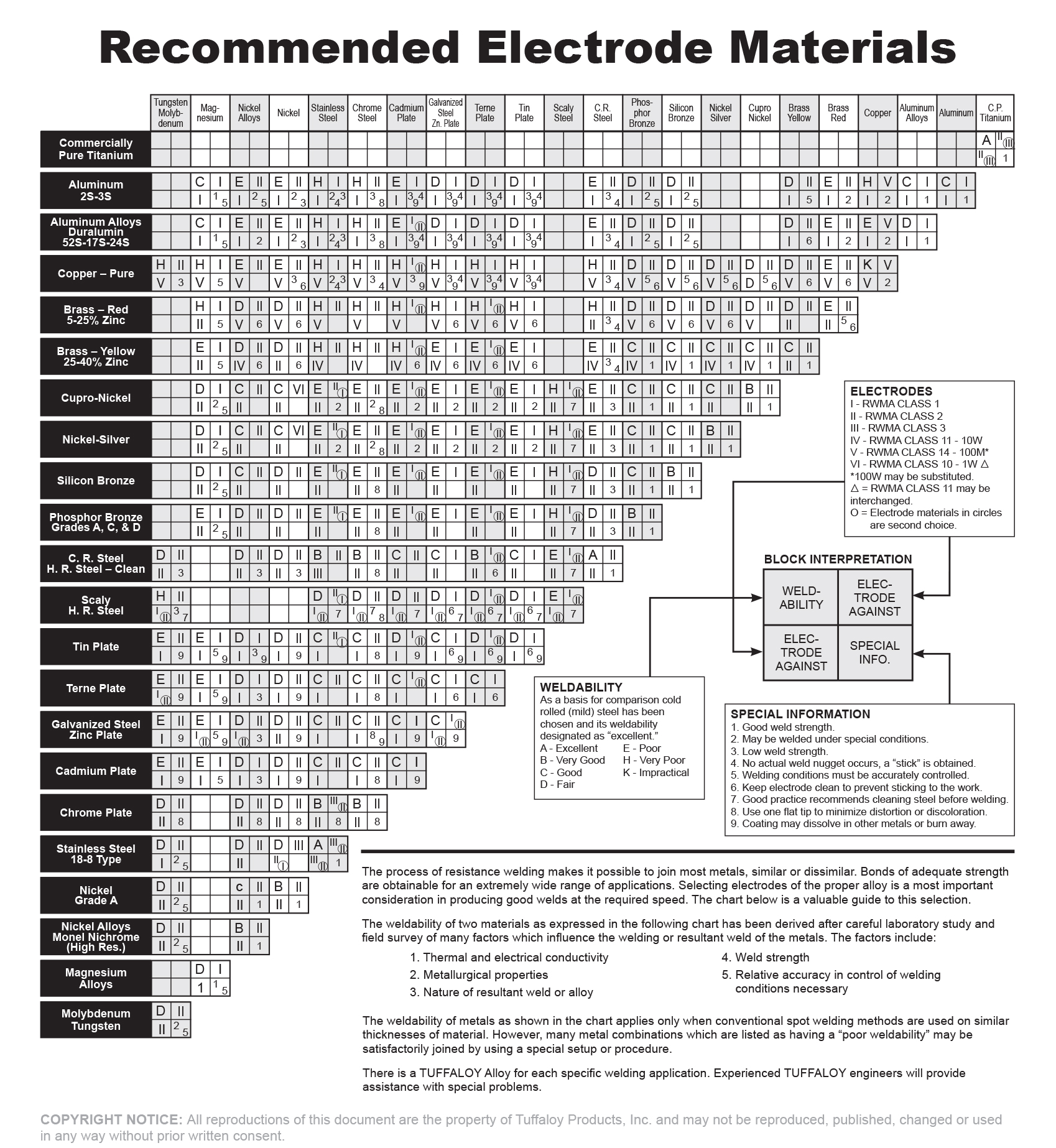
Tuffaloy Products Catalog - Recommended Electrode Materials
Both Zinc and Tin are relatively low melting point materials with modest strength. Their bonded strength to themselves or other materials is relatively weak compared with the base material they may be bonded to. Galvanized steel bonds are made with nuggets into the steel not the surface zinc. High strengths are obtained. If only the zinc is melted and bonds a very weak joint is formed with the zinc acting as a semi brazing material. Tin coated materials will act the same.
The resistance weldability of copper is very poor. This is due to its high conductivity. Reference materials for the weldability of materials state that resistance welding copper to itself is impractical.
As an alternative a resistance braze may be the only way to get a reliable bond of copper to copper. A coating of zinc or tin is a step in that direction. As stated in the first paragraph they may melt and form a bond to hold the copper members together. Zinc and tin can fail this task because they are not strong and not reliable braze materials. This is addressed in another artricle:
CAN COPPER BE RESISTANCE WELDED?
If better more reliable strengths are desired a true resistance braze using tried and true braze material in the joint would be a better choice to join copper. See the article in this blog:
Reference: RWMA - Resistance Welding Manual 4th Edition
Tuffaloy Resistance Welding Products Catalog - “Recommended Electrode Materials”
Aluminum is very conductive and therefore Has a very small resistance. To make up for this a very high current is required to generate heat per JOULES LAW.
If your equipment has the capability to deliver enough amperage and force then it can be used to weld aluminum.
Resistance welding requirements run:
• Amperages of 30,000 – 50,000 amperes would be common power requirements for aluminum using AC equipment.
• Additionally relatively high forces are required to contain the weld and forge the weld nugget. Forces of 5kn (1150 lb.) force up to 20 kn. (4500 lb.) can be expected.
• Weld times can run from 8 to 30 cycles.
This data is for:
Alloy 2024 Thickness from 0.64 mm (0.025 in) to 3.18 mm (0.1.2 in)
If your welder has the power and duty cycle capability to perform the above then you can weld aluminum. Your local machine distributors will be able to help you make this determination.
Different values are available for midfrequency powered systems. They will be similarly higher than the normal steel values.
Reference: AWS Standard C1.1 - Recommended Practices for Resistance Welding
RWMA – RWMA Resistance Welding Manual 4th Edition
The answer to this question can be found in this blog and in many available references. References are listed below and an abbreviated table is listed here. You and your customer must decide upon the acceptable specification and then produce the product accordingly. The data provided here is a guide that does work but can vary from machine to machine. The exact settings must be determined by trial and error.
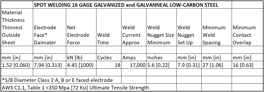
Slight modifications of these values will work for bare non coated steel.
A full list of materials and thicknesses and associated weld schedules can be obtained in AWS Standard C1.1. The RWMA Manual offers a full background in Resistance Welding including Machinery, Electrical and all components. The Tuffaloy Products Catalog offers weld schedules.
Related Article:
What are the typical resistance weld schedule settings to weld 1mm to 2mm low carbon steel?
References: AWS Standard C1.1 - Recommended Practices for Resistance Welding
RWMA – Resistance Welding Manual 4th Edition
Tuffaloy Products Catalog
Page 2 of 44
Have a Question?
Do you have a question that is not covered in our knowledgebase? Do you have questions regarding the above article? Click here to ask the professor.