
Spot Welding
Questions and Answers
All resistance welders including spot welders are designed with industrial cooling systems. The water supplied to these systems can be supplied from wells or city water. This water enters this industrial machine with a water-cooling system which was not cleaned or designed to carry drinking water.
The used water is then discharged to a sewer system or in most cases sent into a recirculating system. The recirculating system is usually a COOLING TOWER or CHILLER designed to cool the water back to a desired temperature. These systems may be open to the environment or closed. The water may be treated with industrial chemicals to maintain its cooling characteristics and insure free flow. This water returns to the spot welder. Well or city water is used as make up for evaporation or lost water. Water in these systems is not meant for human consumption.
The medical implications and dangers of drinking welder cooling water are beyond the scope of this blog.
Reference: RWMA – Resistance Welding Manual 4th Edition
There are many reasons that could cause welds to fail specifications. The components and factors and set ups that must be evaluated to correct these situations have been discussed in depth in this blog. Some of the items that my need to be examined are:
Machine design or function
Control
Transformer
Conductors
Connections
Bad Weld Schedule
Inconsistent weld schedule
Bad pressure
Electrodes overheating
Lack of proper water cooling anywhere
There are many pages already written about each of these items in this blog. I will not boar you with a repeat here. Do a search and read about the importance of each item and how it can affect the weld nugget.
This was not a complete list. Plant air, water and power were not mentioned. Other items also apply.
A WEAK OR NO WELD
To start a general evaluation of failing spot welds one might start with the basics by turning to this blog:
WHY DO MY WELD NUGGETS GET TOO SMALL AFTER AN HOUR OF WELDING?
This is a good starting point for spot welds and can lead to many of the other topics listed above which can be found by doing a search by subject or phrase in this blog.
If you are interested in projection welding then I would suggest one starts with the following article:
WHAT ARE THE COMMON FAILURE MODES FOR PROJECTION WELDING?
This is a good place to start an investigation which can potentially lead to a solution for your situation.
Additional searches in this blog may be needed to learn about the control, transformer, other components and how they make resistance welding possible.
Weld schedules may be needed from Catalog or AWS sources. Examples and data is here in this blog.
References: RWMA – Resistance Welding Manual 4th Edition
AWS C1.1 Recommended Practices for Resistance Welding
AWS J1.2 Guide to the Installation and Maintenance of Resistance Welding Machines
Tuffaloy Resistance Welding Products Catalog
CMW Welding Products Catalog
Nut welding is performed every day to bare steel, galvanized, stainless and other materials.. Basic data is available to give one starting points to begin. Published data for MFDC is not readily available but will be similar. Welds will happen in in much shorter times equal faster. Start at lower weld times and work up is the rule for all new set ups.
There is another article in this blog which describes the many variables to consider for a proper weld schedule to nut weld stainless steel. Start with this and you will be guided to other references which can help you develop a good process.
HOW DO YOU DEVELOP A PROCESS TO PROJECTION WELD STAINLESS STEEL?
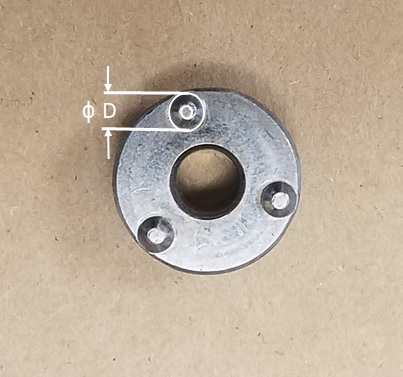
THREE PROJECTION WELD NUT
Reference: AWS C1.1 Recommended Practices for Resistance Welding
AWS J1.3 Specification for Materials Used In Resistance Welding Electrodes and Tooling
AWS J1.2 Guide to Installation and Maintenance of Resistance Welding Machines
Photos courtesy of T.J. Snow Co. and Tuffaloy Products Inc.
Resistance weld processes are set up at the proper settings to produce good weld nuggets at the beginning of the operation. Unfortunately, spot welding electrodes all wear with use. This means the face expands in size/diameter. This is generally called mushrooming.
SEVERE MUSHROOMING
If the face expands, the initial starting current would now be passing through a larger surface area. The current density will be decreasing. Essentially the weld area will be cooling down. If it cools the nugget gets smaller and eventually the nugget will fail to meet the required specifications.
This is fully described in another article
How do I determine a tip dressing frequency or program a spot welding electrode?
Due to mushrooming, there are only two options:
• dress the electrode back to original dimensions before the nugget is unacceptable
• increase the weld current at a rate to match the weld face growth
An article that addresses current increase is:
WHEN THE ELECTRODE FACE AREA CHANGES AT WHAT RATE SHOULD THE RESISTANCE WELDING CURRENT CHANGE?
There are several articles on this subject in this blog. Just search for “Dress”
Reference: RWMA – Resistance Welding Manual 4th Edition
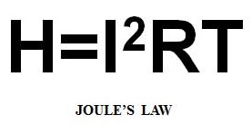
Bare steel and galvanized steel of the same thickness run at very similar weld schedule settings. The electrodes are the same. They vary in the amount of current or time applied due to the coating of galvanize (zinc) on the surface. This coating reduces the contact resistance and makes the overall resistance in the joint lower. More current or time must be applied to compensate for the reduced total joint resistance to reach the necessary temperature to form a nugget. The heat is generated by Joules Law:
The galvanized coating (Zinc) coats and alloys with the copper electrodes. This can result in:
• Increased the rate of electrode mushrooming
• Electrode face sticking to the part
• More frequent dressing
• Increased electrode wear
• Reduced electrode life
• Increased expulsion at weld initiation
Electrodes welding bare steel can make many thousands of welds. Welding galvanized steel they may only last a few hundred up to a two thousand before dressing is required.
Most operations work out schedules that allow for dressing or electrode changes at breaks or shift changes. In these operations they use current steppers to increase the current a few amperes each weld to match the electrode face growth until the next dressing or change. Then they reset the control counter and begin again.
Some operations use robotic dressers that move in every so many welds between part changes to slightly kiss the electrode face and renew the face continually. Then the current remains constant.
The basic resistance welding equipment can remain the same for bare or coated steel. The settings must change to compensate for the zinc coating. All resistance welders have the ability to do this. Due to the galvanized coating, dressing frequency enters into the process and must be addressed. Manual, pneumatic or automated systems can be used.
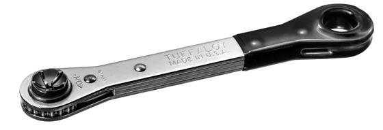
HAND DRESSER
Many modern controls have the stepper functions to compensate for electrode face growth. This is used to increase the time between dressing.
A related article in this blog is:
WHAT IS THE BEST METHOD TO SPOT WELD 16 GAGE ELECTROGALVANIZED SHEET METAL?
References: AWS Standard C1.1 Recommended Practices for Resistance Welding
RWMA - Resistance Welding Manual 4th Edition
CMW Inc. Welding Product Catalog
Page 4 of 44
Have a Question?
Do you have a question that is not covered in our knowledgebase? Do you have questions regarding the above article? Click here to ask the professor.