
Spot Welding
Questions and Answers
As stated in other articles in this blog copper is a very conductive material and has little resistance and will not heat up very much. Copper electrodes are not used. RWMA Class 13 or 14 refractory materials are used. They heat up and transfer heat into the copper. In many applications the copper is coated with a low melting material, which will melt and act as a brazing agent and bond the surfaces together. This joint can only be as strong as the interface material. Zinc and Tin are commonly used but are not very strong. This limits their effectiveness.
A better joint can be formed if a true resistance braze is performed by placing actual braze material in the joint. Heat this joint using the same resistance method until the braze material melts and fills the joint and is allowed to solidify under very modest pressure. Don’t squeeze the molten braze material out of the joint. This braze joint will be strong and durable.
Low Force Adjustable Holder
The following articles in this blog will further explain resistance brazing.
How do resistance brazing schedules vary from spot welds?
Resistance brazing is used regularly in the electrical industry to make attachments in their highly conductive copper and silver products.
References:
CMW Products Inc. Catalog
Tuffaloy Products Catalog
RWMA, Resistance Welding Manual, Section 6
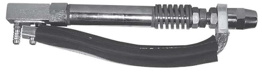
Welding a ferrule on the end of braided wire is done frequently to reduce the cost of assembly of electrical devices. Unfortunately, published process are not available.
The ferrule and the wire are copper or copper alloy. They may be coated with a plate or a varnish. Since heat in resistance welding is generated by resistance, resistance welding copper does not generate heat readily. People that perform ferrule welding generate the heat by using a hot electrode like RWMA Class 14 – Molybdenum.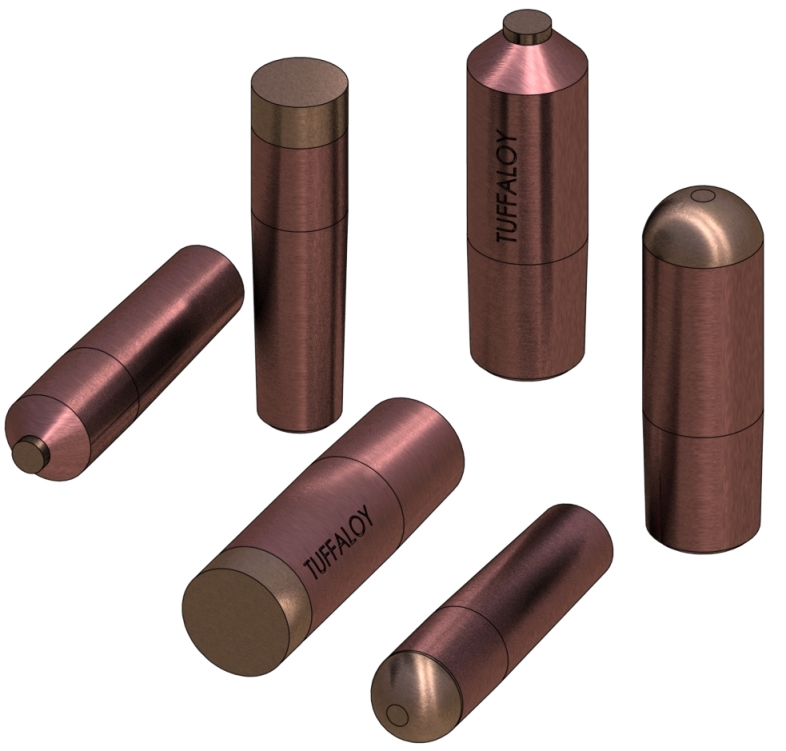
REFRACTORY FACED ELECTRODES
The heat is generated in the electrode, which then is transmitted into the ferrule and the wires. As they heat up the ferrule plate and wire varnish is melted or burned away and the wires and ferrule begin to bond under the pressure of the welder.
The actual weld conditions/schedule will have to be developed by trial and error.
Reference: RWMA Resistance Welding Manual 4th Edition
Burnout is a term that I am not familiar with. This term implies two possible events:
• Expulsion at the electrodes
• Transformer Failure
I will look at each of these individually.
EXPULSION
This refers to expulsion of hot material from the weld face area. Numerous articles have been written on this subject in this blog:
WHY DO I HAVE EXPULSION AT THE WELD INTERFACE?
WHY DO I HAVE SURFACE EXPULSION?
Each of these articles list many reasons for expulsion. Each of those reasons has it’s own article in this blog explaining how it affects the weld and expulsion.
Do a search for the individual listed reasons and read the articles.
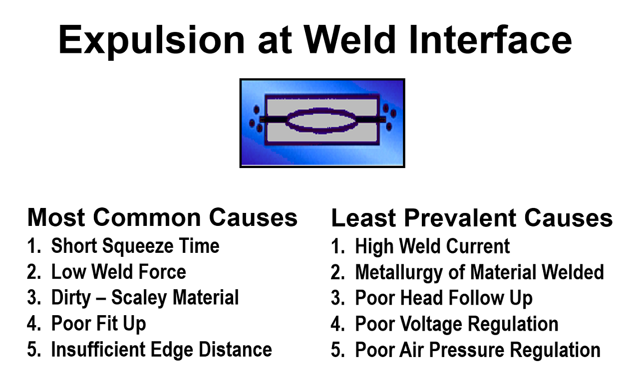
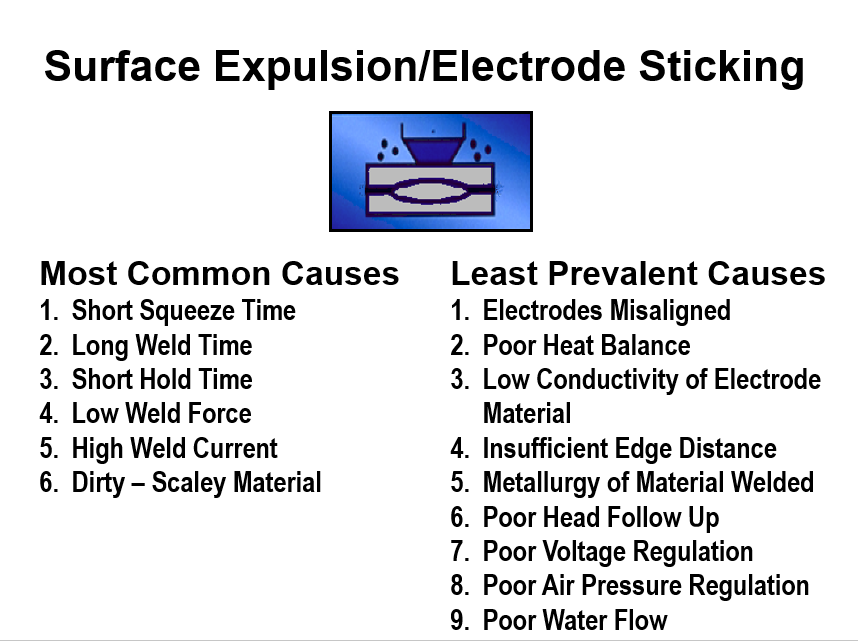
Expulsion leads to severe/accelerated electrode wear and is dangerous for personnel nearby. It also can coat machine parts and the product being welded with weld flash.
TRANSFORMER FAILURE
The other definition of BURNOUT could be failure of the transformer. There are only two general concerns for transformer users:
• Overheating
• Drawing more power than the rating for the transformer.
The fix for this is ensure that the transformer has the proper water flow as required by the manufacturer. Secondly confirm that the transformers are operating within the rating limits litsted on the manufacturers attached label.
Beyond this transformer issues and testing need to be addressed with the manufacturer of the equipment. Equipment design and maintenance is not in the realm of this blog.
References: RWMA – RWMA Resistance Welding Manual 4th Edition
AWS – AWS Standard J1.2 Guide to Installation and Maintenance of resistance Welding Machines
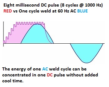
Yes, there is an article which refers to high frequency welding use in the marketplace. There is very little use of high frequency, because it is not practical at this time.
The article which describes this situation is:
What are the differences between 1000 and 4000 Hz frequency resistance welding systems?
References: RWMA - RWMA Resistance Welding Manual 4th Edition
Aluminum has a strong tendency to form aluminum oxide on the surface virtually as fast as it is exposed to air. This is the reason that aluminum can be difficult to spot weld. One must break through this nonconductive aluminum oxide thickness in order to conduct current. Once accomplished there is a weld nugget which in turn will form aluminum oxides. Additionally, there are other unnamed oxides from the copper electrodes on the surface of that nugget. This combination can vary from weld to weld.
When this is part is electroplated the chemicals in the plating bath will react with the part and weld nugget according to the chemistry it encounters. Some of these nugget chemistries are turning black others are not. Not knowing the chemistry of the plating bath or the part face chemistry no answer can be offered.
A comment must be made that anodized aluminum is made in a plating bath. Have you created an anodizing environment? Partially?
There is an electrochemical reaction present creating the black nuggets vs nonblack nuggets.
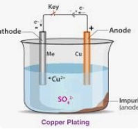
COPPER PLATING SKETCH
REFERENCE: RWMA - RWMA Resistance Welding Manual 4th Edition
Page 3 of 44
Have a Question?
Do you have a question that is not covered in our knowledgebase? Do you have questions regarding the above article? Click here to ask the professor.