
With MFDC and DC one generally considers the reactive impedance as very small in resistance welding. This is correct once the current is at steady state. Impedance is a combination of reactance and resistance in the welding circuit. In MFDC and DC the reactance during a weld is minimal as compared to a 60 Hz AC weld. However thare are still some effects of inductance that play a part in MFDC and DC resistance welding. Inductance is a property of a conductor that resists the change in current over time. This occurs at the beginning and end of a weld, when the current starts and stops flowing.
In the initial and final cycles when the current is changing, inductance does have an effect upon the process of MFDC. As the weld initiates the control measures the current each half cycle and realizes that it did not reach its desired current due to the inductance. The control will fire at full conduction during this time. This repeats until the desired current is reached. This is called rise time and is 3-8 milliseconds for MFDC. At this point the current is at steady state and the inductance goes to zero and the current levels off until the control turns the current off. When the control turns off, the inductive energy that was stored in the circuit will now bleed off. There will be a decreasing current flow until all is bled off. This is called decay time and is about 3-8 milliseconds.
DC equipment which operated at 60 HZ operates similarly but will have a different curve and take longer to reach steady state.
Plots of the output curves of both MFDC and DC will exhibit small ripples. These ripples reflect the electrical sine wave which has been rectified to 1000 HZ or 60 HZ.
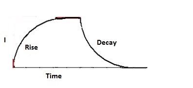
RED REPRESENTS NO INDUCTIVE LOSSES
BLACK SHOWS THE RISE AND DECAY RESULTING FROM
INDUCTIVE LOSSES
These inductive losses can be compared to a fly wheel. To get it started, extra energy must be put into the flywheel to get it turning, rise time. Once the target speed is reached no extra energy is required. It will continue at speed. When it is time to stop the energy of the spinning wheel must be removed to stop the wheel, decay time.
As discussed MFDC and DC will have different rise and decay curves.
Each welder potentially will have a different inductive load.
Reference: RWMA – Resistance Welding Manual 4th Edition
AWS – Welding Journal, Q & A, July 2019