
Controls & Transformers
Questions and Answers
Duty cycle for all RWMA equipment is designed to operate at a maximum 50% duty cycle. For each new resistance welding application one must confirm this value will not be exceeded.
The AC and DC duty cycle calculations can be found in another article:
Power calculations can be found in the article:
HOW MUCH POWER IS USED RESISTANCE WELDING ON A 150 KVA WELDER?
Reference: RWMA – Resistance Welding Manual Section 19.3
An MFDC or AC weld gun is just a working tool that does what it is told to do by one or more controls. The robot puts it in place to make the weld and the resistance welding control makes all of the decisions for the welding schedule. The gun is not adaptive. The robot positioning is not adaptive but can be repositioned. The weld control in some cases can be adaptive.
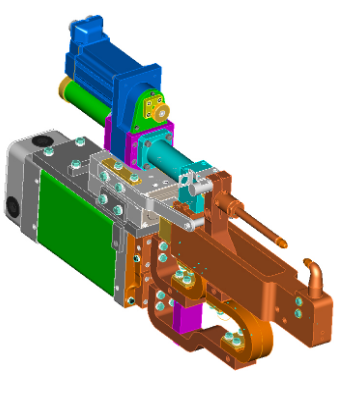
SERVO ACTUATED WELD GUN
The amount of adaptability and diversity depends upon the control. A discussion of adaptive controls is beyond the scope of this blog. One should contact your local supplier and control manufacturer to expand your knowledge on adaptive controls.
RWMA could be a source of equipment manufacturers with knowledge in this area.
Reference: RWMA - Resistance Welding Manufacturing Alliance
Transformer replacement or upgrading will depend upon the type of machine or robotic gun that is involved. The electrical system and physical systems must also be considered.
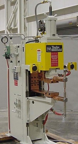
PRESS WELDER AND TRANSFORMER
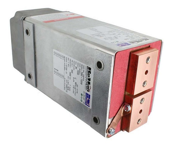
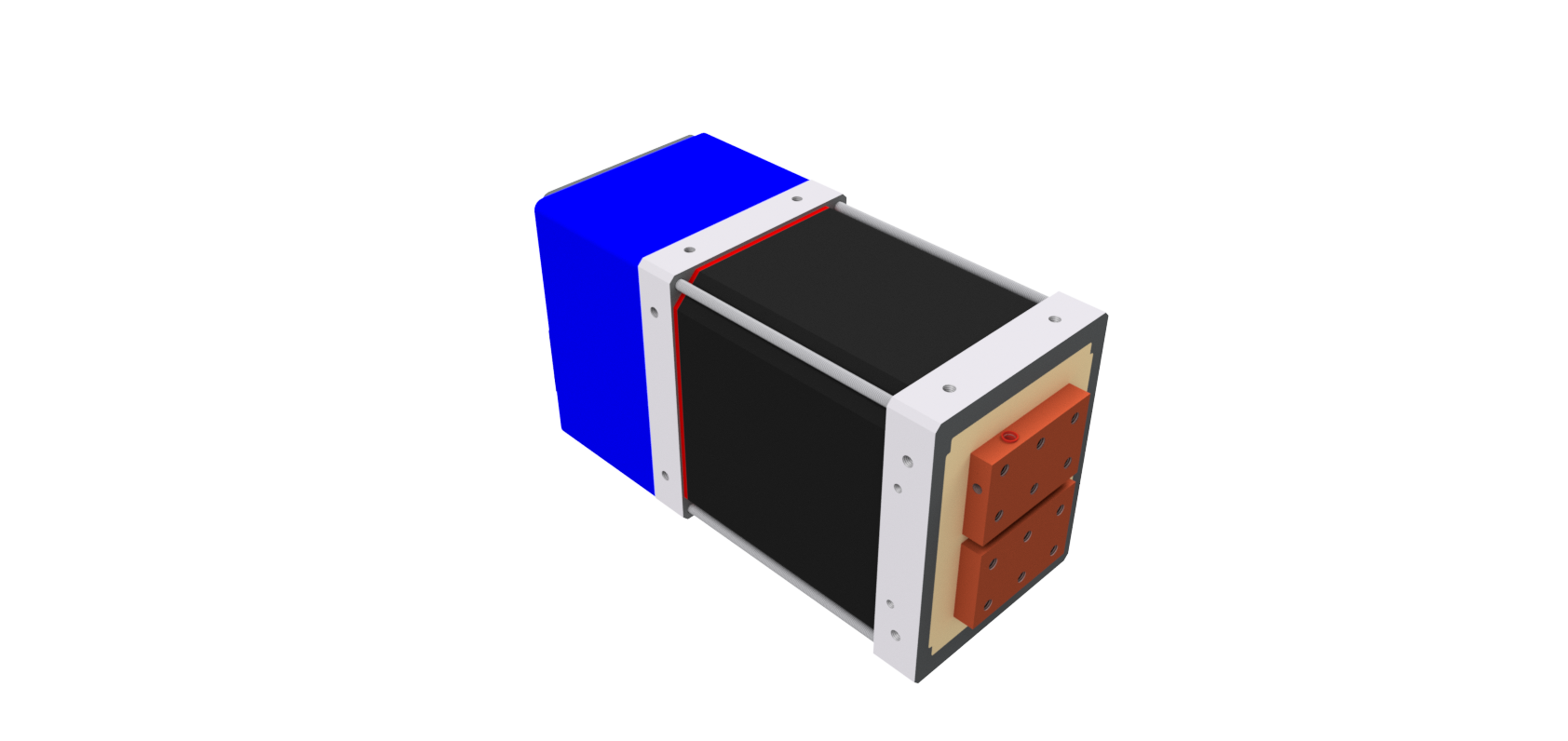
SERVO ACTUATED TRANSGUN AND MFDC TRANSFORMER
The process to change out a transformer varies by machine and application and is beyond the scope of this blog. Consult with local Machine builders and Distributors in your area for the best input on how to replace or rebuild equipment.
References: AWS Standard J1.2 - Guide to Installation and Maintenance of Resistance Welding Machines
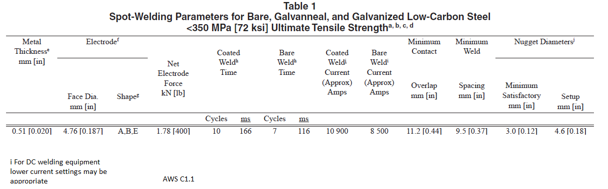
There is no simple way to determine the power for a spot weld job. To determine the power requirements, one must know the approximate weld schedule. Weld schedules are dependent upon the product being welded. For every application one must know the material, thickness and any coating. What are the weld nugget specifications if any. At this point one goes to sources for weld schedules. An article in this blog covers this:
WHERE CAN I FIND WELD SCHEDULES?
Weld schedules will provide an approximate amperage and length of time for current flow. As discussed in the above article many other critical data are provided necessary for set up including electrode selection, force and resultant weld nugget. These schedules do work.
With the amperage and time and the number of welds per minute and parts per hour one can back into the duty cycle and power. With the weld schedule and the data just mentioned you could read the article:
HOW DO YOU SIZE A RESISTANCE WELDING TRANSFORMER?
The current values and data found in the weld schedule are used here to calculate the transformer size. With the transform determined the appropriate machine can be chosen to weld the product.
One can always turn to local machine or transformer suppliers and they can help with evaluations and give guidance.
References: AWS C1.1 Recommended Practices for Resistance Welding
RWMA – RWMA Resistance Welding Manual 4th Edition
CMW Resistance Welding Products Catalog
Tuffaloy Resistance Welding Products Catalog
This answer has been given in the reverse mode in another published article:
HOW MANY PRIMARY AMPS WILL A 64 KVA RESISTANCE WELDING TRANSFORMER PULL?
If you look at this referenced article, several important data points are necessary in order to calculate the output of the 10 KVA transformer. The turns ratio being the first. The turns ratio shows that power in the primary equals power in the secondary. Secondary voltage is a second necessary data point.
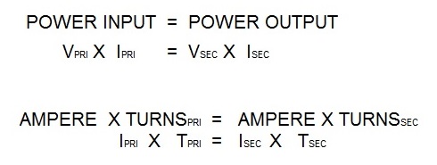
The actual current will be influenced by the secondary circuit.
If you know your turns ration and primary amps at least an estimate can be made. If you measure the input versus the output voltage you have an estimate of the turns ratio for that set up. If there is a tap switch on the transformer one can change the secondary voltage. Then all of the calculations change. Do study the above document so that duty cycle and all factors are considered.
For additional assistance contact a local equipment manufacturer or distributor.
References: RWMA - Resistance Welding Manual 4th Edition
Page 5 of 40
Have a Question?
Do you have a question that is not covered in our knowledgebase? Do you have questions regarding the above article? Click here to ask the professor.