
In flash welding wheel rims there are two potential paths for the current to flow. One is across the faying surface being flash welded. The other is through the circumference of the material from one electrode all the way around to the other electrode. This is potentially a dead short. The question is which path has the least resistance? That will be the current path.
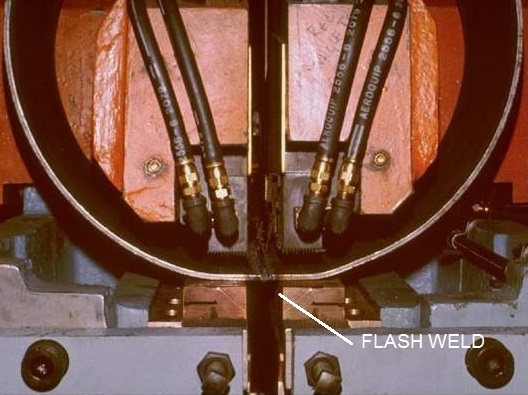
WHEEL RIM WELDER
The resistance to current flow in material is defined as:
R= (Resistivity x Length) / Area
The cross sectional area is equal in the path between the electrodes or around the circumference. The material is the same. So the resistivity is equal. The only difference is the distance. One is approximately an inch the other is the full circumference. If the circumference is 20 inches, the resistance is roughly twenty times greater around the circumference. It is safe to say the resistance is much larger around the circumference than across the faying surface, at any diameter.
OHM’S LAW States:
I = V / R
I= Current
V= Voltage
R= Resistance
Therefore once the two faying surfaces come into contact and flashing begins, little if any current flow would occur through the circumference of the part/material.
All of the electrical energy will be concentrated at the faying surface heating the weld area.
Reference: RWMA - Resistance Welding Manual 4th Edition