
To calrify this issue attached is a previous article which shows the sequence of changes from the initial three phase 60 Hz AC input through several combinations of frequency and waveform changes to the final MFDC 1000 Hz output.
The ripple in the MFDC plot represents the 1000Hz frequency. The entire MFDC curve is on the positive side of the sine wave. MFDC does have a rise and decay of 3-8 milliseconds before and after full current is reached. This appears in the plot as an upslope or downslope. This should clear up the any questions. AN ARTICLE ON MFDC RISE AND DECAY IS ALSO AVAILABLE.
WHY or HOW DO MFDC CONTROLS CHANGE CURRENT FROM AC TO DC TO AC TO DC?
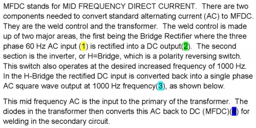
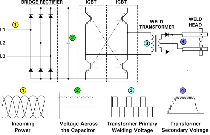
Schematic of Power Conversion In Control and Transformer of Mid Frequency Inverter
The advantage of MFDC is that the weld current has no zero cross overs so it heats the part quickly. Also, it is DC so there are no inductive power losses or problems with magnetic material in the machine throat.
Generally the plant power requirement is reduced substantially with the 3 phase input. Another advantage is robot payload. Higher frequency in the transformer allows the iron core to be smaller. This is a weight reduction which is significant on the end of a robot arm.
Reference: ENTRON Controls, LLC